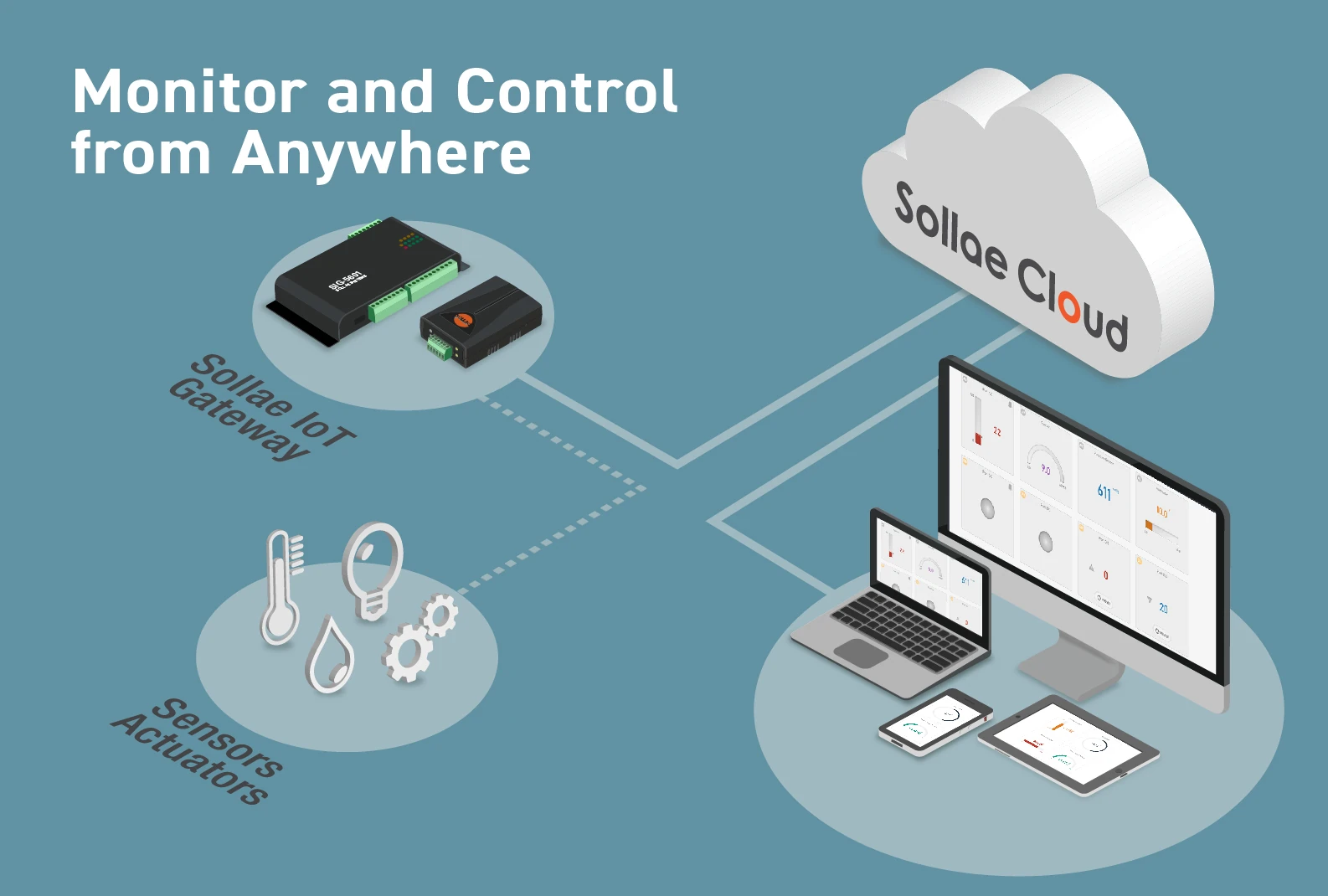
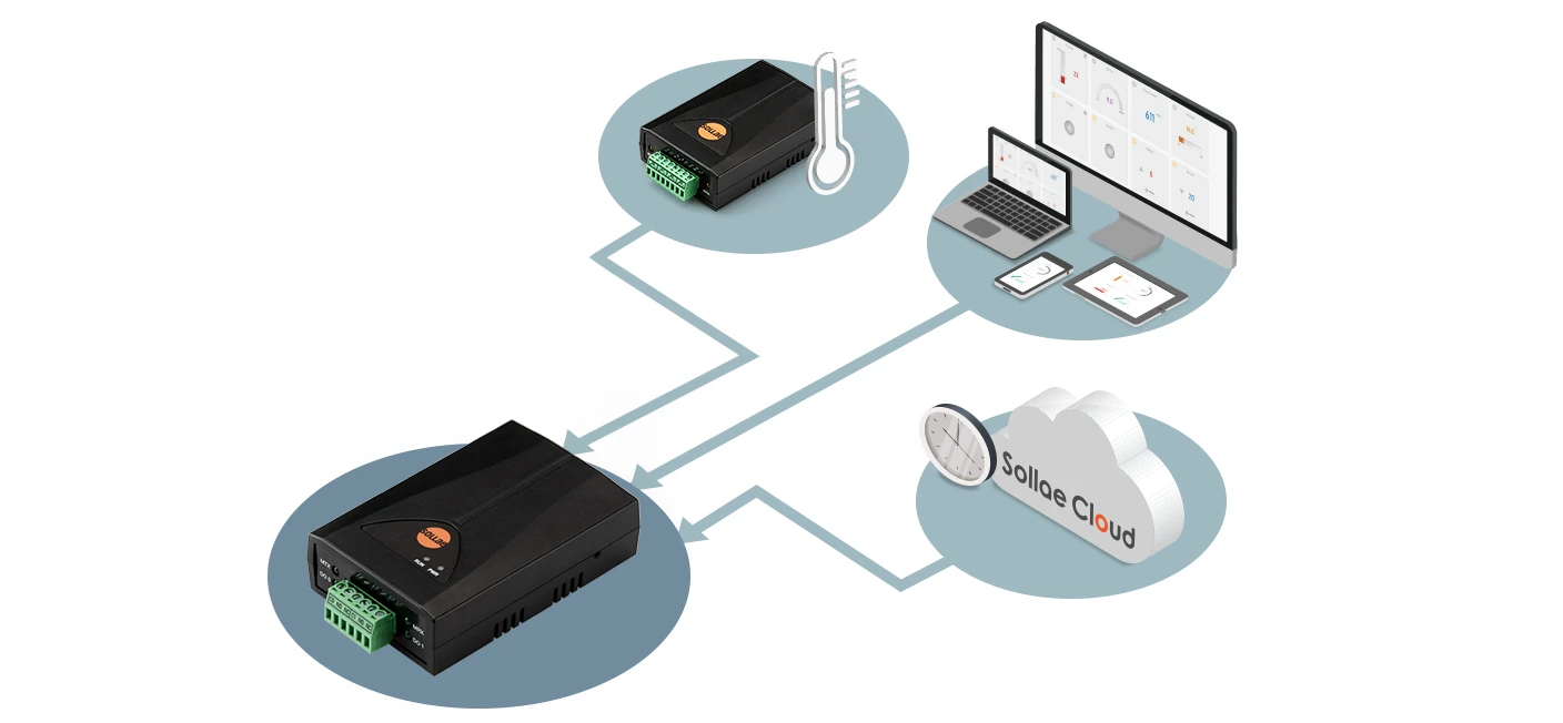
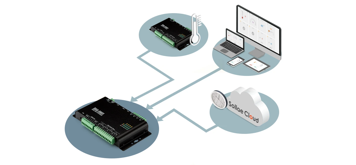
Sollae Cloud is an IoT solution provided by Sollae Systems that paves the way for real-time monitoring, remote controlling, and managing of sensors and equipment connected with Sollae Gateway devices.
What does Sollae Cloud offer?
Quick and easy way to collect data from sensors and equipment
Monitor data in real-time
Control relay output from anywhere
User-defined event and schedule
Event-based output port control
Alarm notification
Email notification
Track device data and activities with the Device Data Logging function
A secure and reliable IoT solution
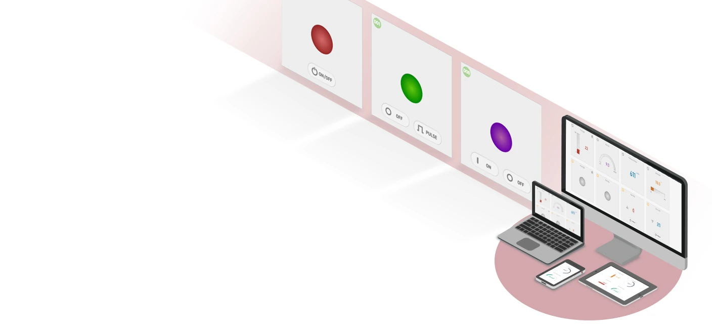
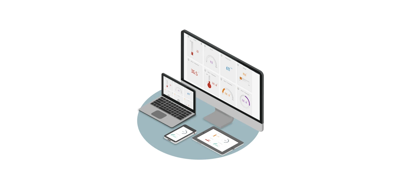
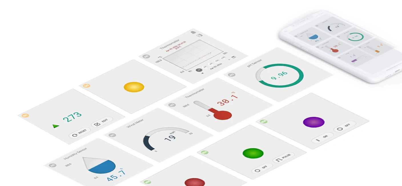
Sollae Cloud's Web Application
Easy to use and allow you to customize the user interface
Visualize real-time data via various kind of widgets and themes
Provide management functions such as monitoring, controlling, configuration, firmware update, etc., all the things you need to work with Sollae Gateway devices remotely
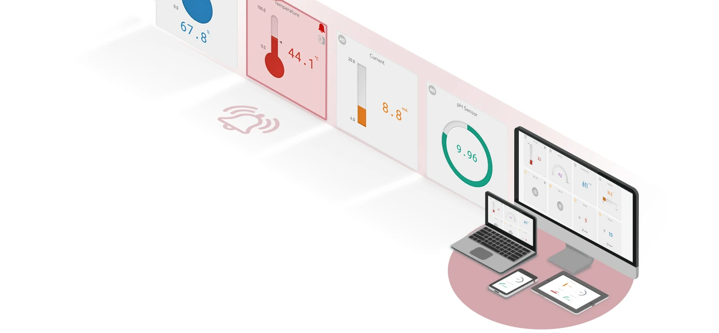
Responsive design, support mobile, tablet, and PC web browsers
Allow multiple access for each account
Support Graphical Editor for designing User Interface
Enable users to view and download device log data for further analysis and monitoring
For better user experiences, it is always recommended to upgrade your web browser to the latest versions.
Supported browsers
Desktop
Chrome version 43 and above
Firefox version 57 and above
Safari version 9 and above
Microsoft Edge version 12 and above
Mobile
Chrome for Android (Android 5 and above)
Safari/Chrome for iOS (iOS 7 and above)
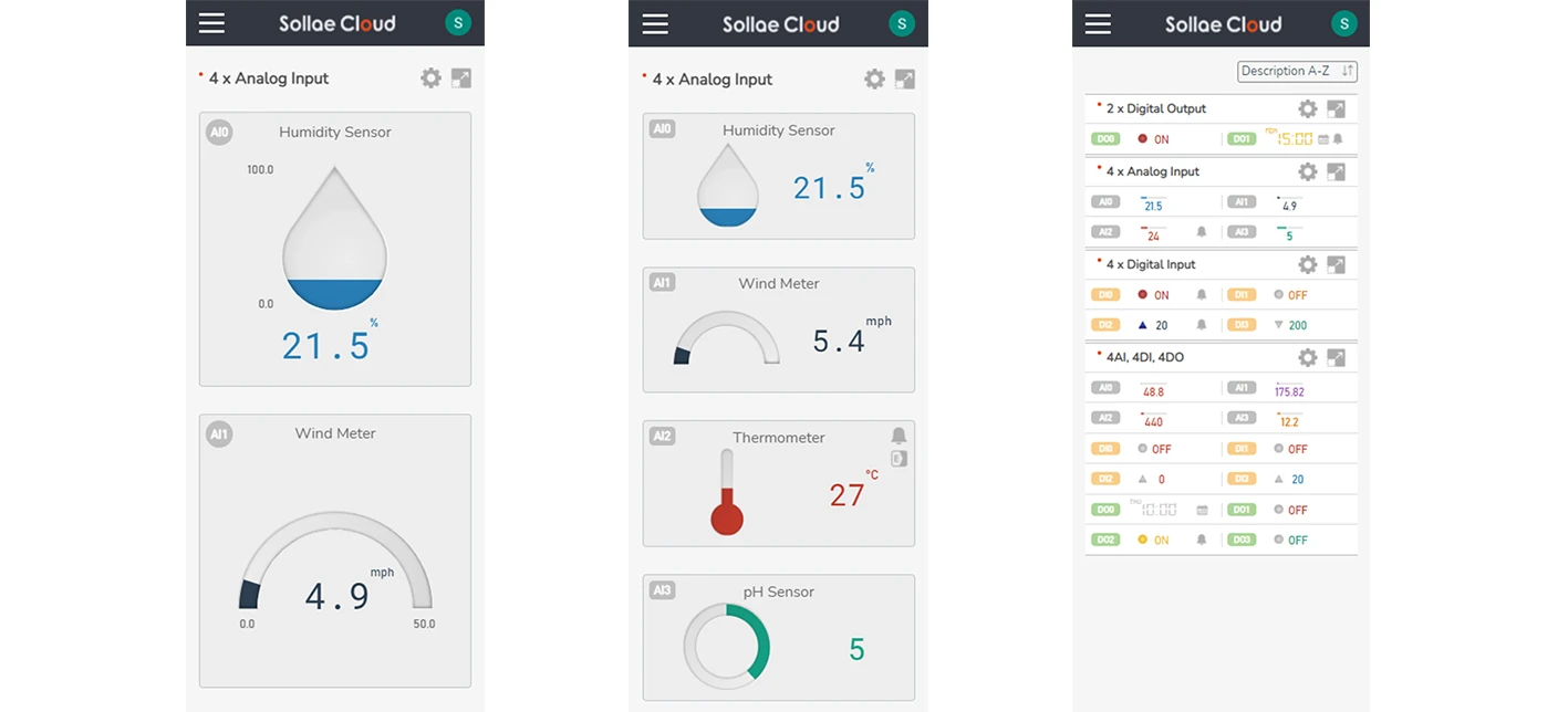
On mobile browsers, you can enjoy major features similar to the desktop version. Note that, currently, the sound effect for Alarm is not supported on mobile browsers. To fully experience all functions of Sollae Cloud Web application, it is preferred to access from desktop browsers.
If you encounter any difficulties viewing images in this documentation, we recommend updating your browser to the latest version.
If you encounter any difficulties viewing images in this documentation, we recommend updating your browser to the latest version.
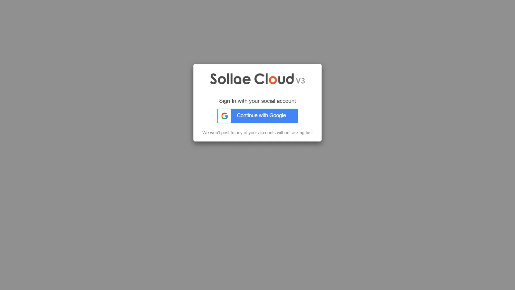
Like other ezTCP products, our design concept favors simplicity, convenience, and security for users. No further signing-up process is required, as we let users use trusted third-party OAuth. Currently, Google OAuth is supported. That means you can just sign in to Sollae Cloud with a valid Google account.
By signing in, you are agreeing to the Terms of Service.
Sign in with a Google account
Visit Sollae Cloud Home Page
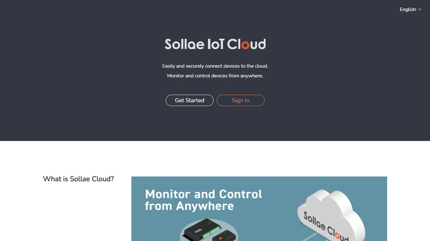
Click Sign In to continue. Here you can sign in with your Google account.
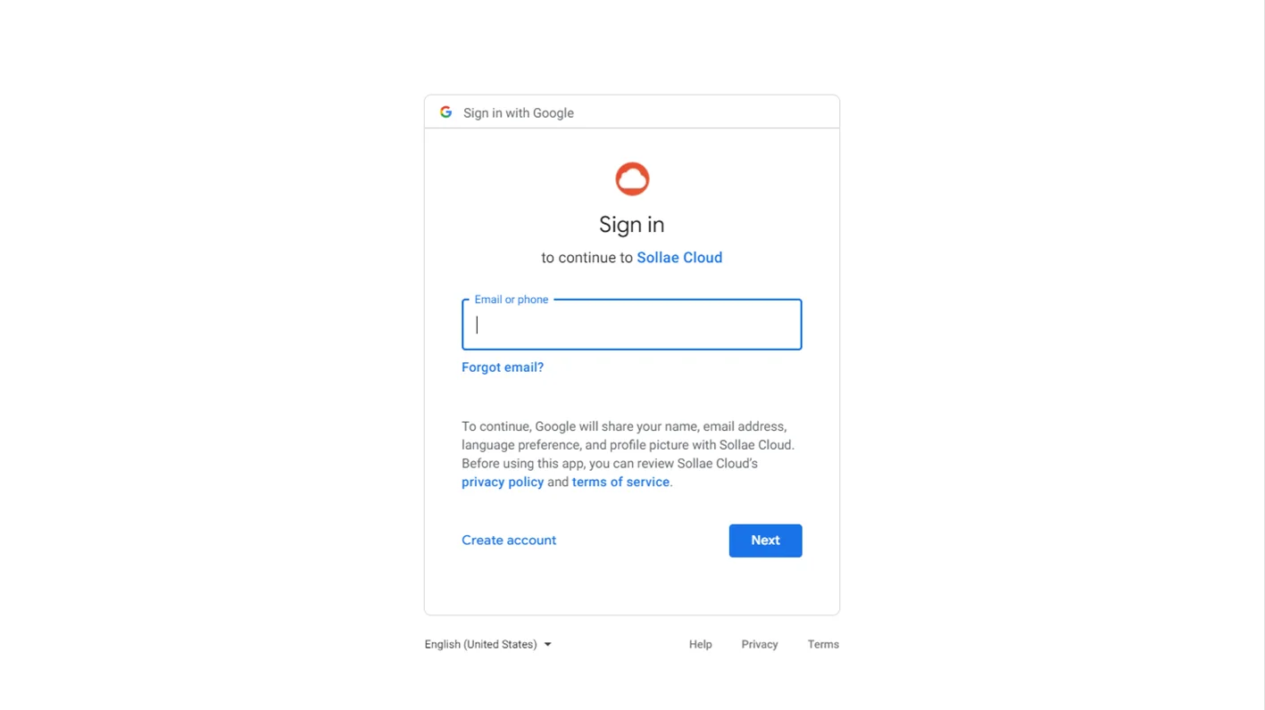
Enter your Google account credentials to proceed.
After signing in successfully, you will be redirected to Sollae Cloud Dashboard Page.
To use Sollae Cloud service, you need to add a valid Sollae device to your ownership by registering it under your account.
Sollae devices are equipped with analog input, digital input, and digital output ports. They are meant to be a bridge between users and the IoT equipment, in that they interface with sensors/equipment on one side and exchange data with Sollae Cloud on the other side.
A Client ID is a unique key value used to identify a Sollae device. In order to register a device to Sollae Cloud, you need to get its Client ID beforehand.
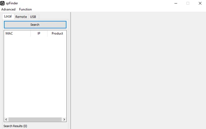
Get the device's Client ID by using spFinder
Refer to the device's user manual to connect your device with spFinder. Normally just plug the LAN cable into a Sollae device and then Search for it on your Local network.
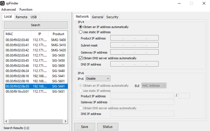
From the spFinder window, select the Sollae device you wish to register.
Navigate to the Security tab and copy the device's Client ID.
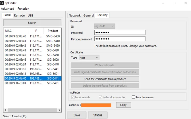
Due to the ownership security concern, we recommend you keep the Client ID of your devices private.
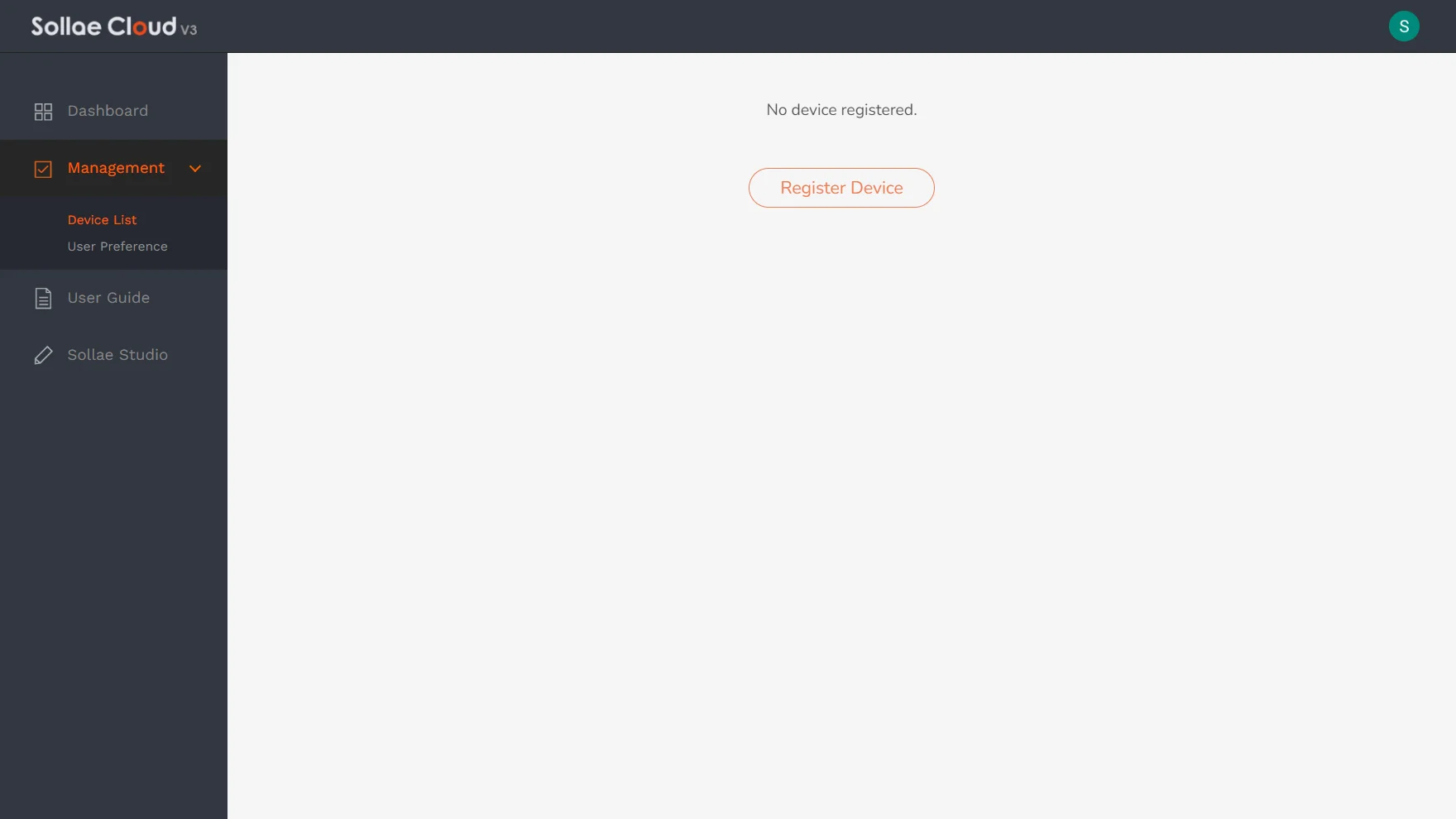
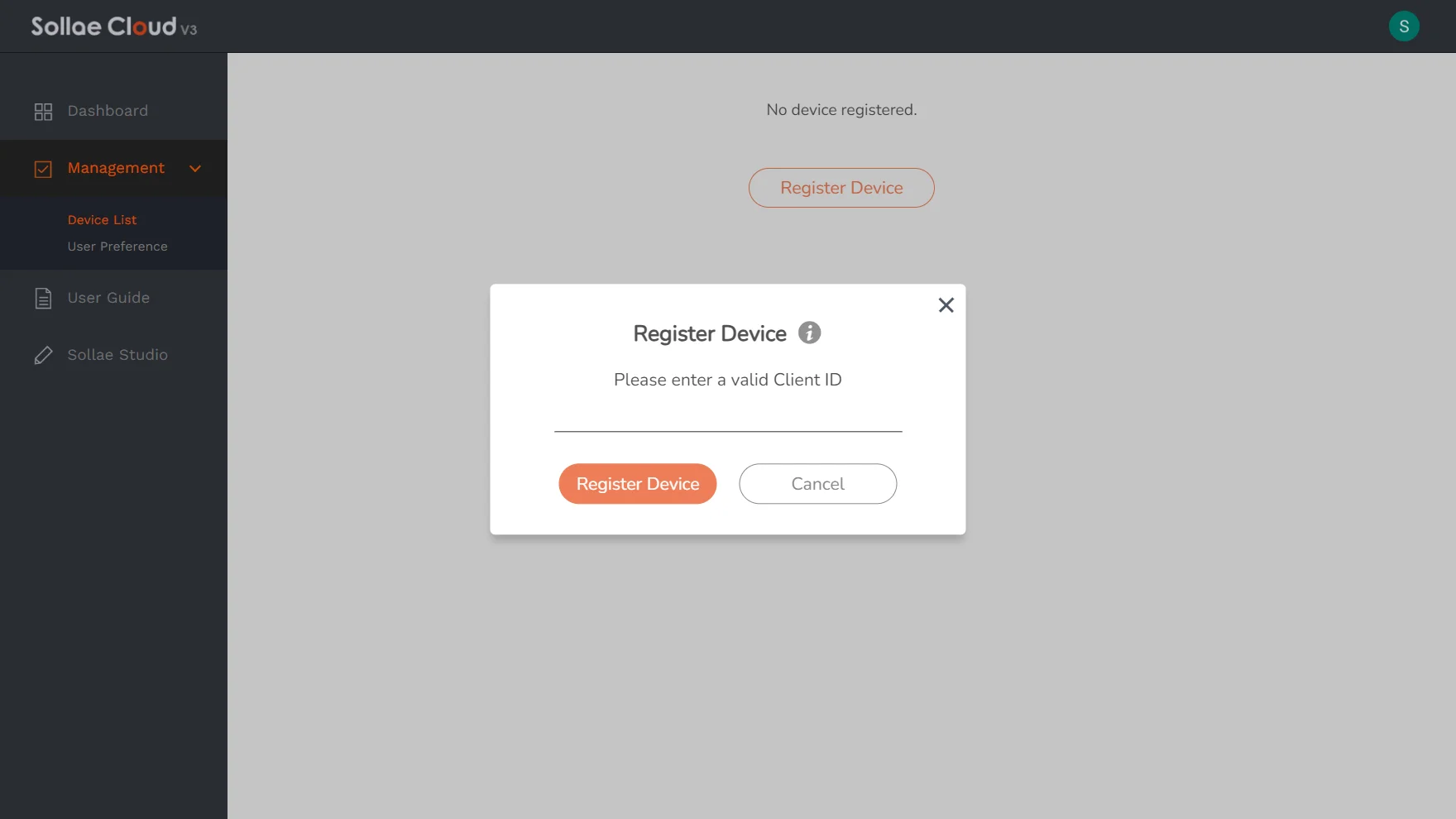
Click the Register Device button
Enter/paste(Ctrl+V) the device Client ID you got and then click Register Device.
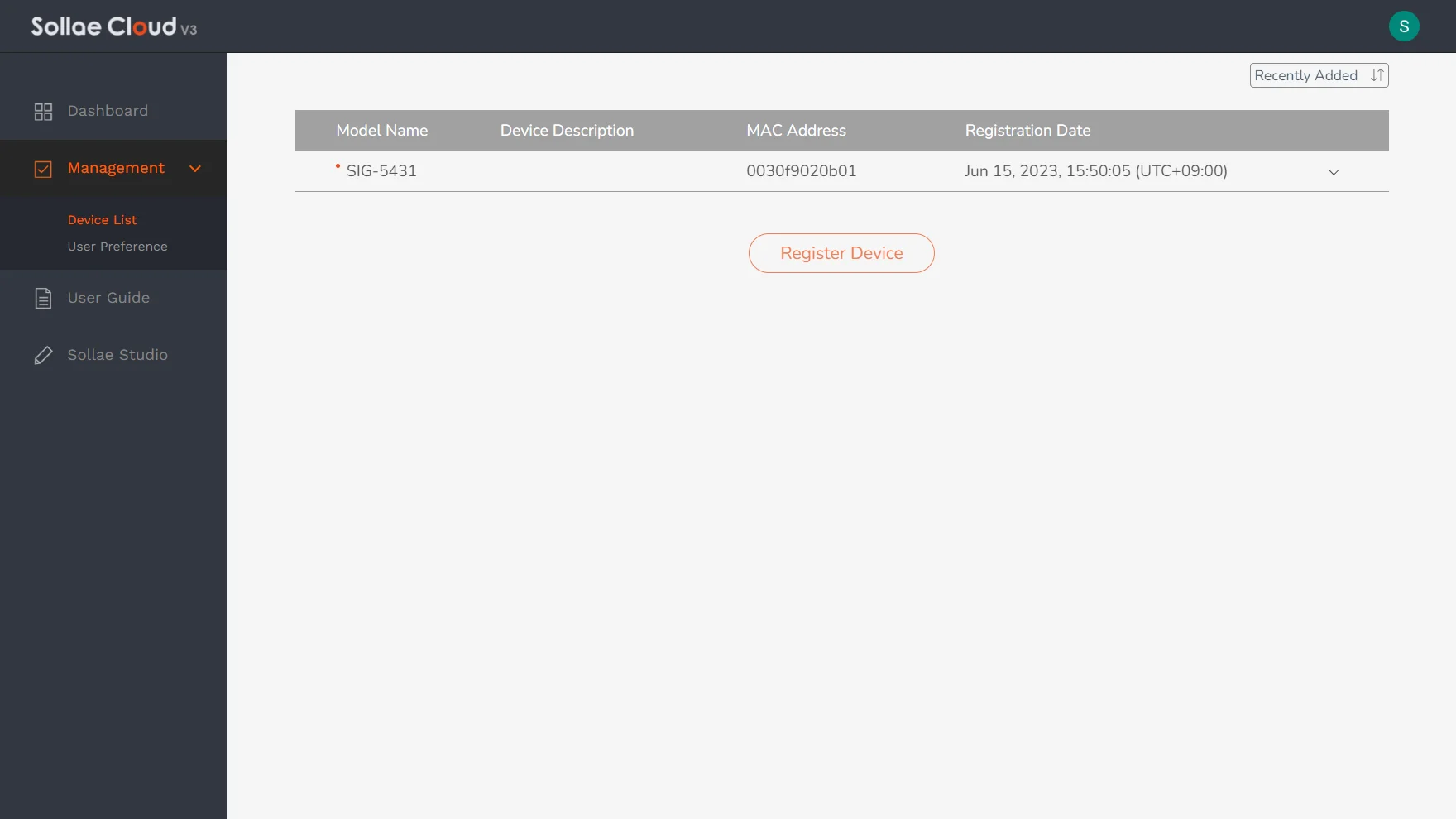
You can view the list of devices that are successfully registered under your account.
A device can only be under the registration of a single account at a time. It is possible to access one account from multiple places simultaneously. The maximum number of simultaneous access = The number of your registered devices + 2. For example, if your account has 3 registered devices, it allows up to 5 access simultaneously. Once a device is registered, if you wish to change its ownership to another account, firstly you need to deregister it from the current account.
Visit Device List
Select the device you want to deregister
Toggle the management view of a device by clicking on a row in the Device List table.
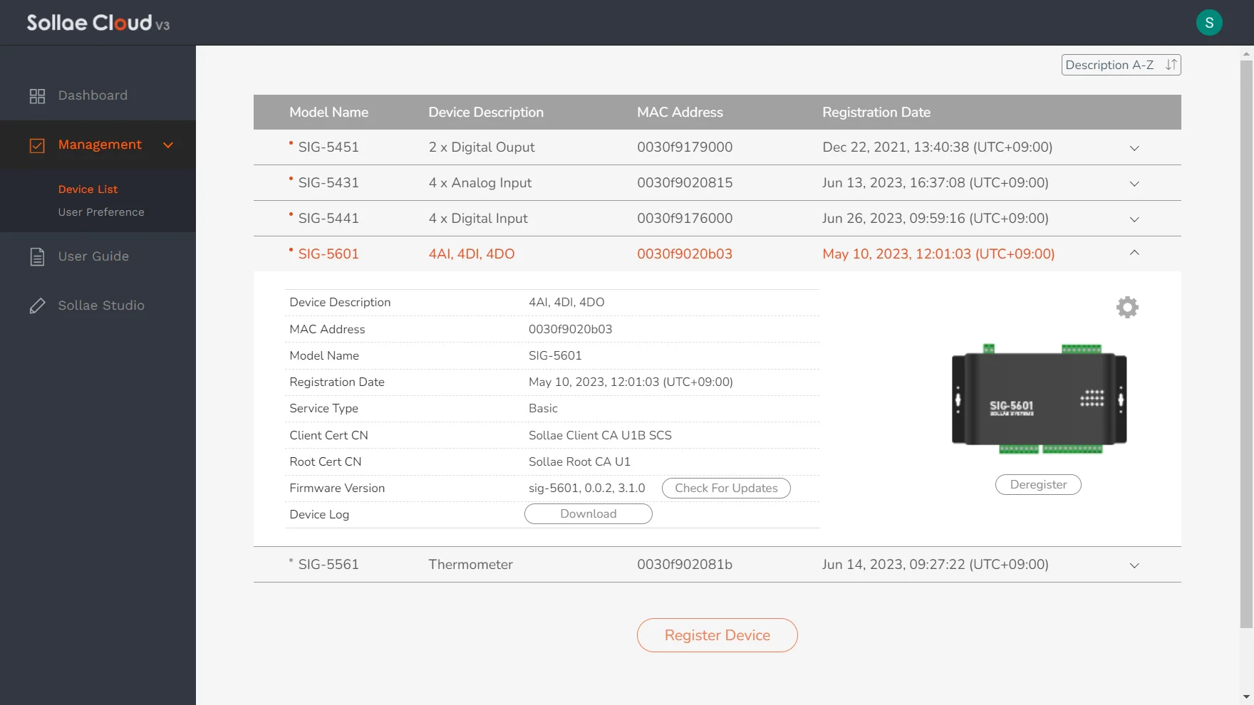
Click the Deregister button inside the device management view
Click Remove Ownership to confirm your decision.
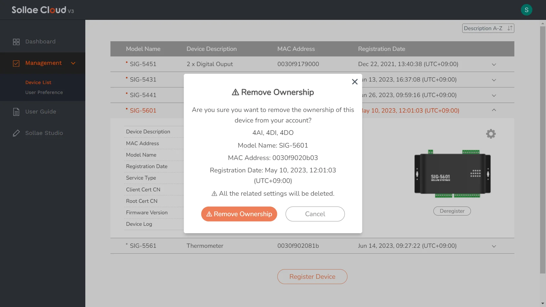
The unregistered device will be removed from your device list, and no longer under your management. Except for the device-stored configurations, all the related settings for the device will be deleted. Once a device is successfully deregistered, you can register it with any account, including the ones that it has been deregistered from.
Please keep in mind that Sollae Cloud communicates and exchanges real-time data with the web app via MQTT protocol over WebSocket. Due to the characteristics of WebSocket on browsers, especially on mobile devices, if the browsing web app is not kept as an open window, the WebSocket session tends to be shut. The browser may not receive any MQTT message when it happens, thus the displayed data may not be updated in real-time. If the situation lasts for minutes, it may cause MQTT connection loss with our server. We can list some example cases:
When the screen is locked.
When you switch to another app on a mobile device.
In case your web app is disconnected from our MQTT server, all the web app functions such as remote controlling, managing, and monitoring will be unavailable. To continue, simply reload the web app to establish a fresh MQTT session with the server.
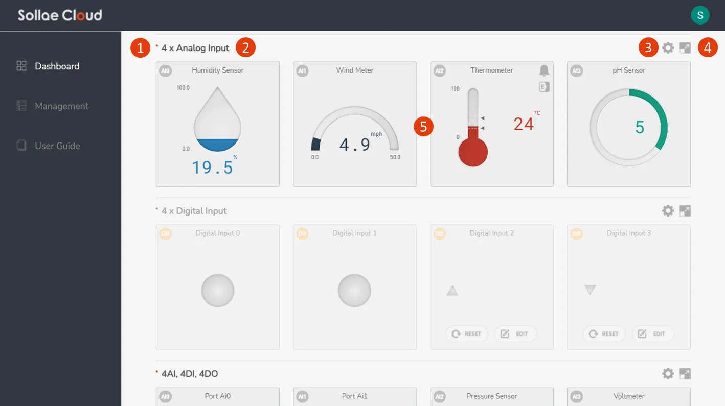
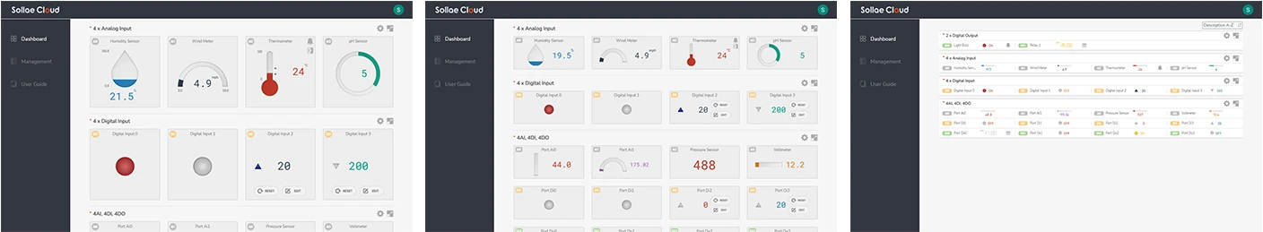
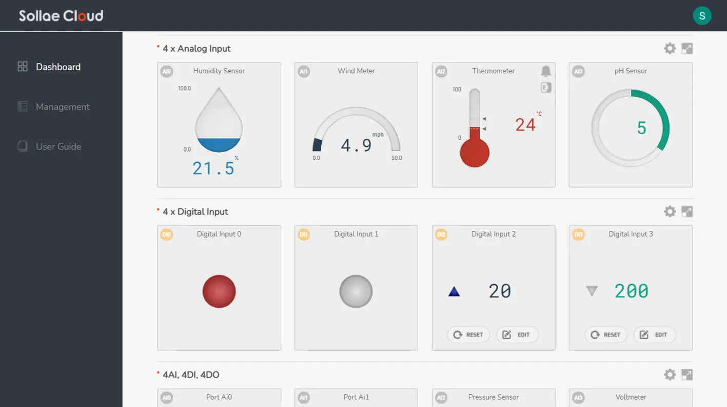
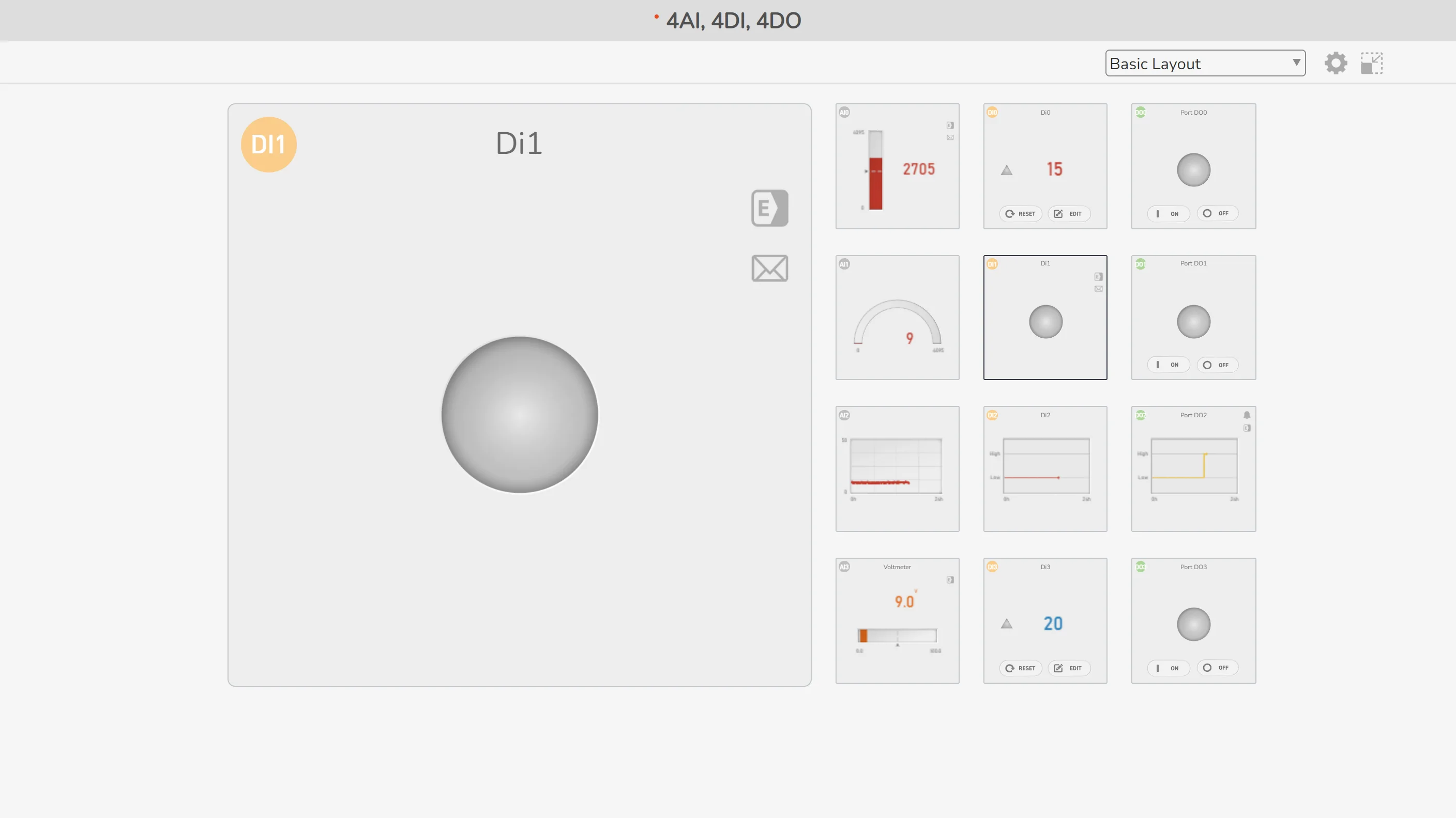
Main window
The main window for monitoring and controlling. All devices registered under your account will be shown here. You can watch the real-time data and manually send the control commands.
Components of a device dashboard
Connection state indicator: Demonstrate the connection state of the device. Gray color means not connected, and red means connected. Note that when your web app is disconnected from our MQTT server, all the indicators will turn gray even if your devices are still connected to Sollae Cloud.
Device Description Panel: Display the device description. If the description is yet to set or set to empty, the device's MAC Address will be shown.
Device Setting Button: Enter the setting page for a device. This is not accessible when the device is disconnected from Sollae Cloud.
Device Expand Button: Expand the view of a single device.
Device Dashboard Panel: Contain the visualization of all individual ports of the device. Each port visualization, or we can refer to as a port widget, consists of a port name label, port description, event/action/alarm/schedule indicators (only turn up if you enable event/action/alarm/schedule for the port), and the data visualization for this port.
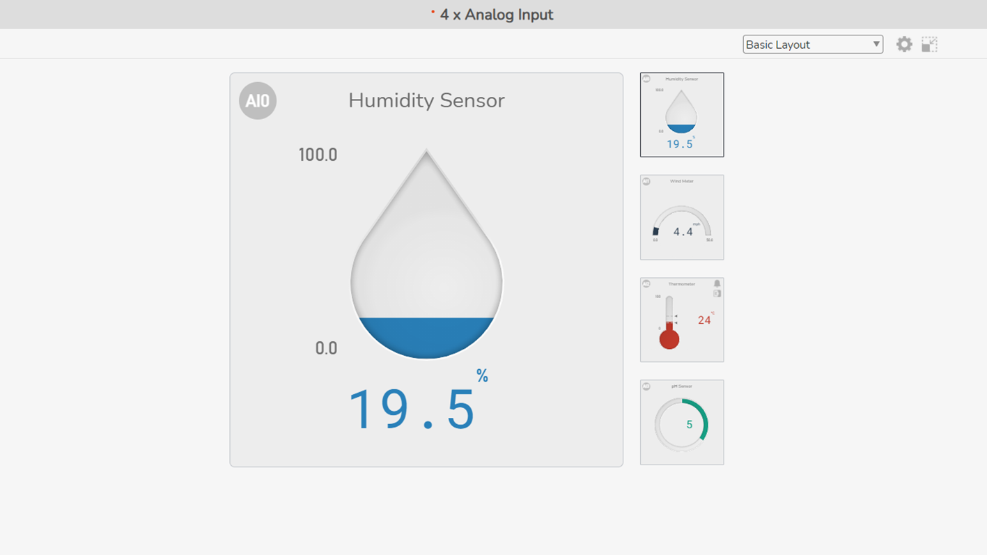
Expanded window
An expanded layout and view of a single device and its ports. This window can be opened from the Dashboard page, by clicking on the Device Expand button, or a port widget.
The expanded view can also be entered from a direct URL:
https://cloud.sollae.com/dashboard/MAC_ADDRESS[/PORT_NAME]
https://cloud.sollae.com/dashboard/MAC_ADDRESS[/PORT_NAME]
For example, a device with MAC Address 0030f9000001 can be accessed from:
https://cloud.sollae.com/dashboard/0030f9000001 or
https://cloud.sollae.com/dashboard/0030f9000001/ai0 to view the particular port AI0.
https://cloud.sollae.com/dashboard/0030f9000001 or
https://cloud.sollae.com/dashboard/0030f9000001/ai0 to view the particular port AI0.
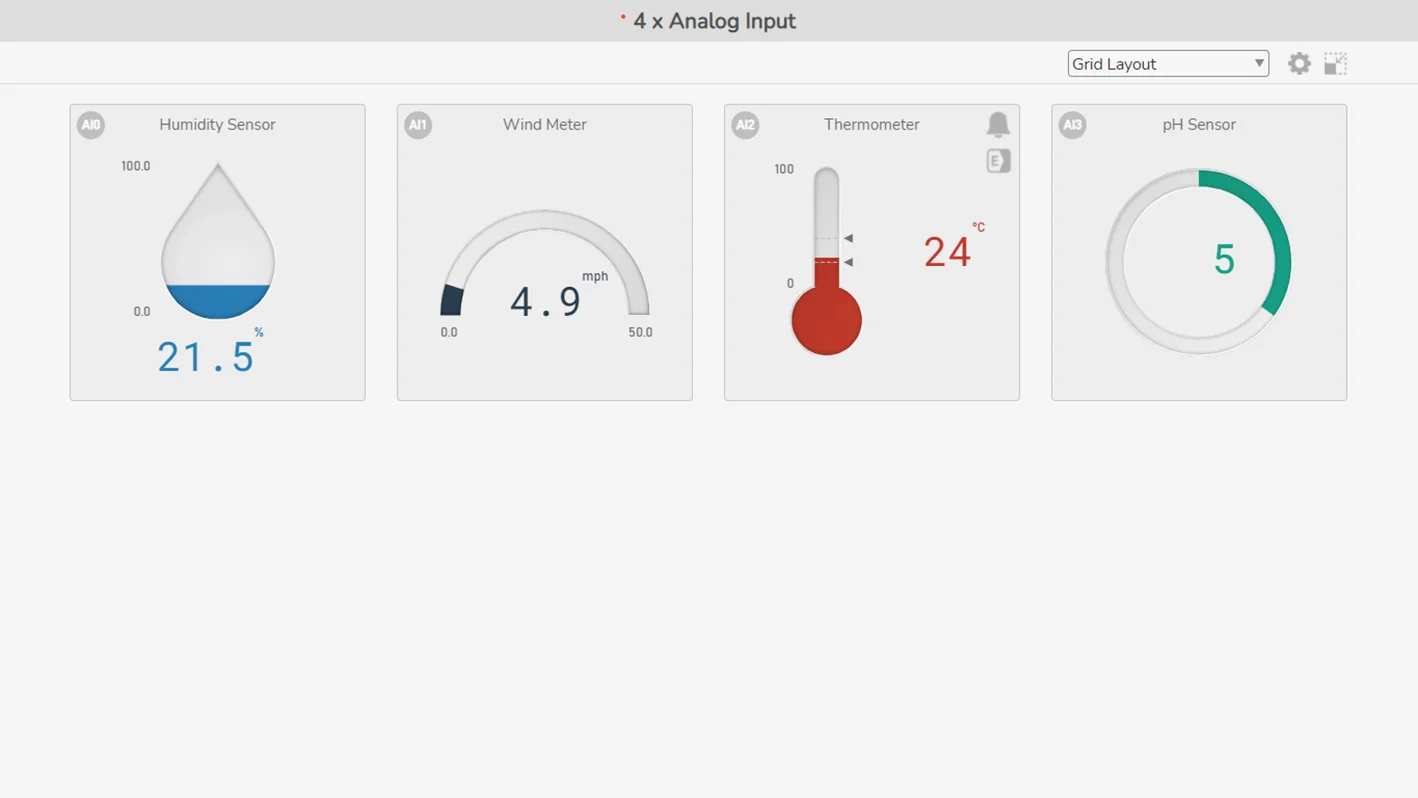
In the expanded window, the device dashboard is always displayed in Normal View, and center-aligned.
Device List
This page displays the list of registered devices. On this page, you can register a new device, view the detailed information of an individual device, deregister, and check for firmware updates.
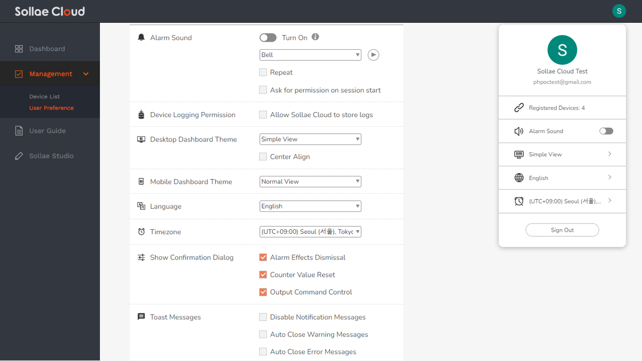
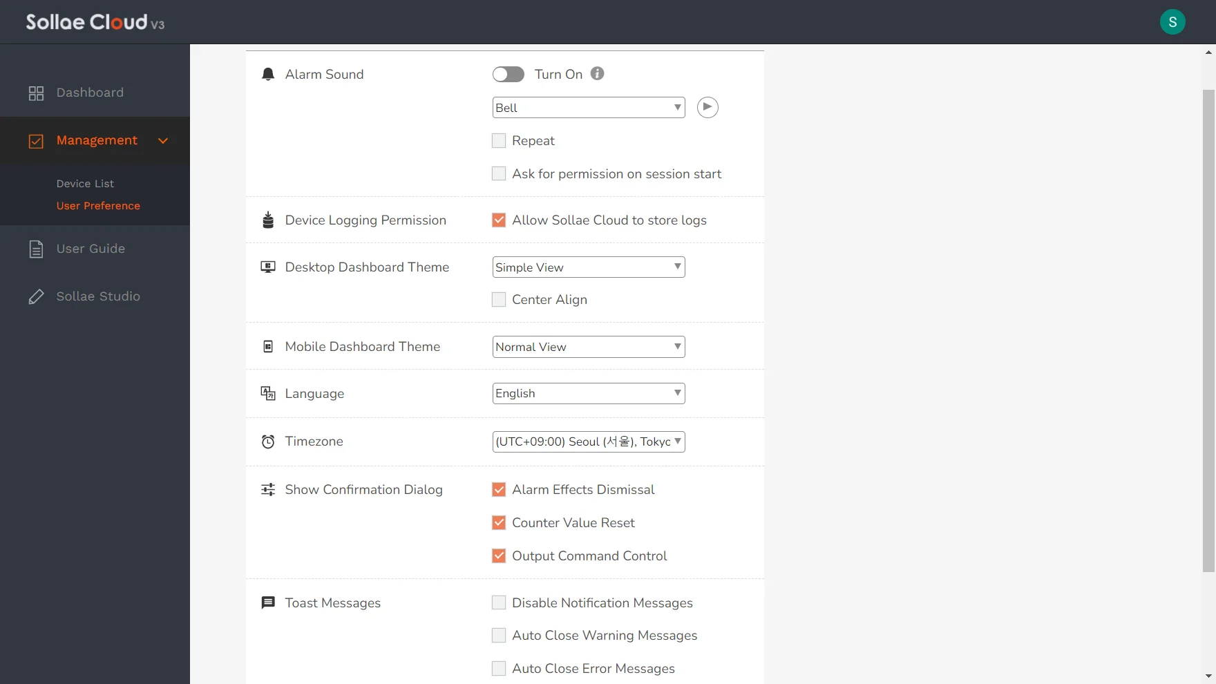
List of User Preference
Alarm Sound (only available on desktop browsers)
Device Logging Permission
Desktop Dashboard Theme
Mobile Dashboard Theme
Language
Timezone
Show Confirmation Dialog
Toast Messages
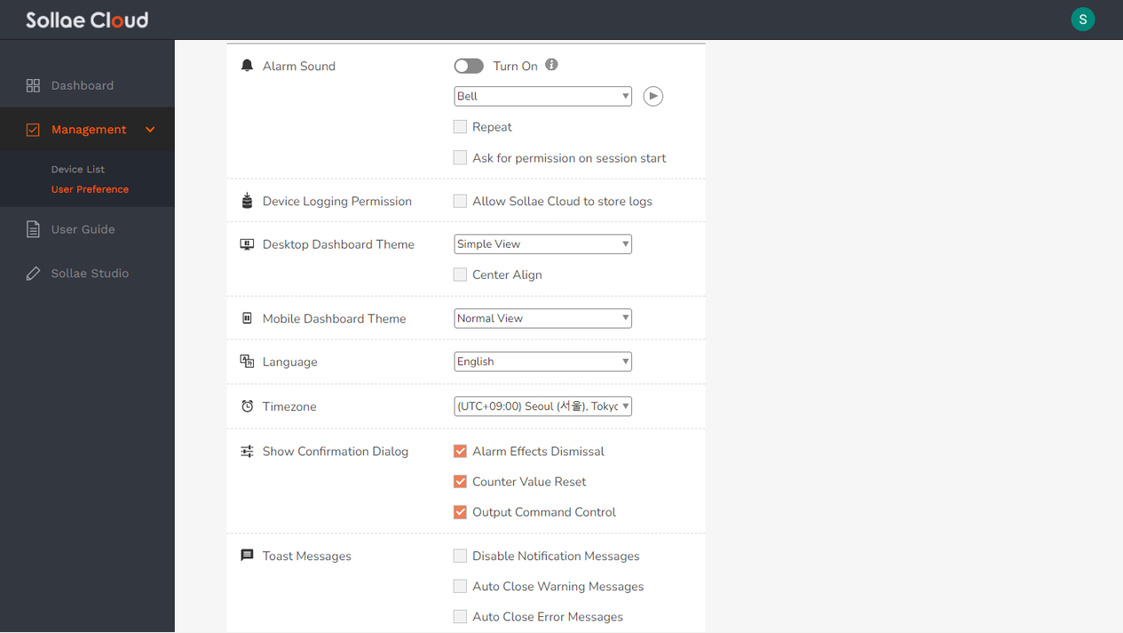
Alarm Sound
Turn On: Enable/disable alarm sound function in the current browsing session.
Sound Files: Choose from the list of available sound files. A sound preview button is also available.
Repeat: Sound will be played only once or repeatedly starting from when an alarm-set event occurs until it is ceased.
Ask for permission on session start: This option is to ensure that the sound effects are always available for alarm. Due to the policy of many browsers, in a browsing session, user interaction is required as consent to play audio. If set, a pop-up dialog will appear on every session's start to confirm alarm sound permission.
Device Logging Permission
Allow Sollae Cloud to store logs: This setting applies to all registered devices for a user account, granting or disallowing Sollae Cloud from storing historical data, including recorded states and related activities. If unchecked, users will be unable to download the device log data using the Device Data Logging function.
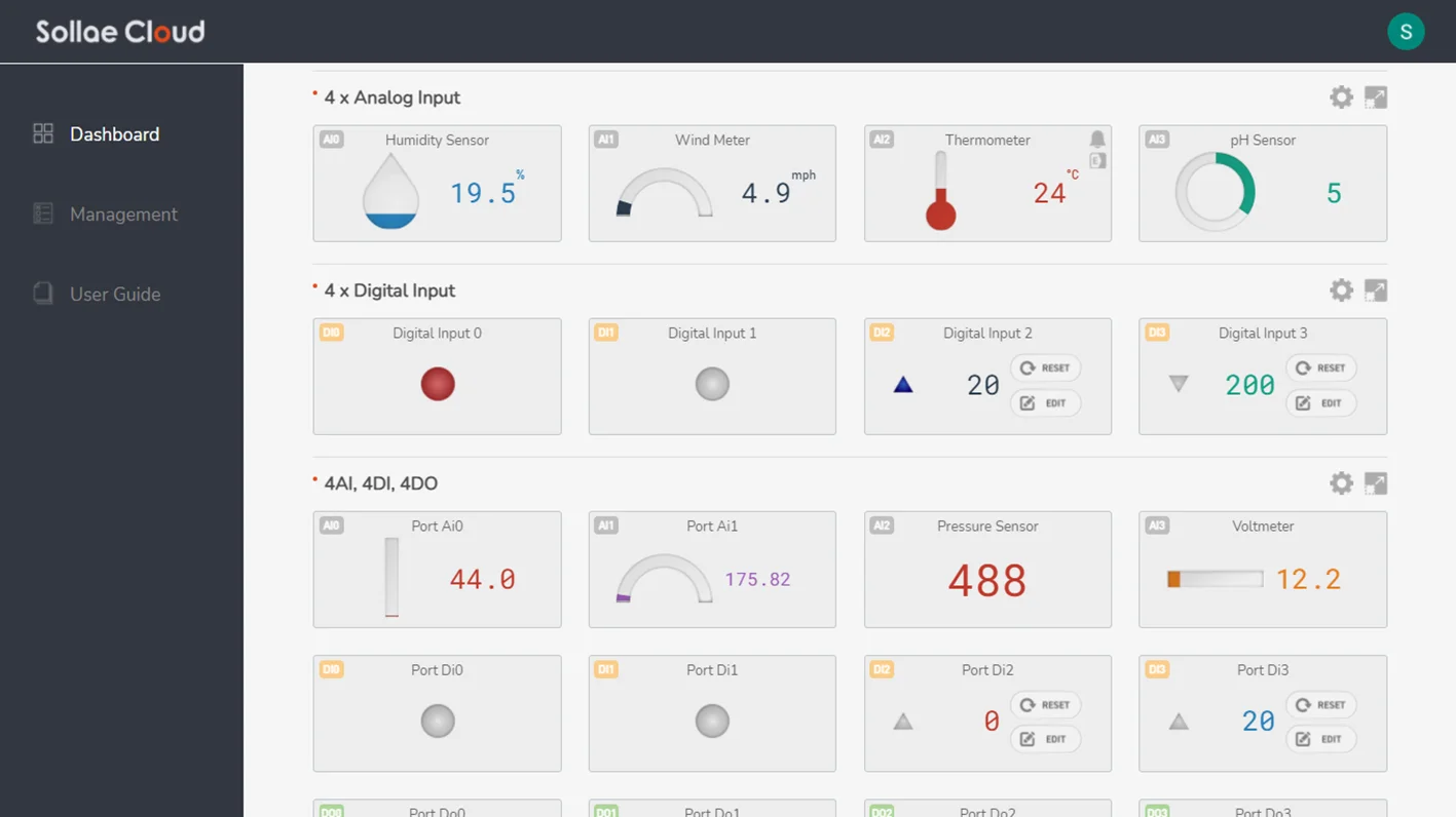
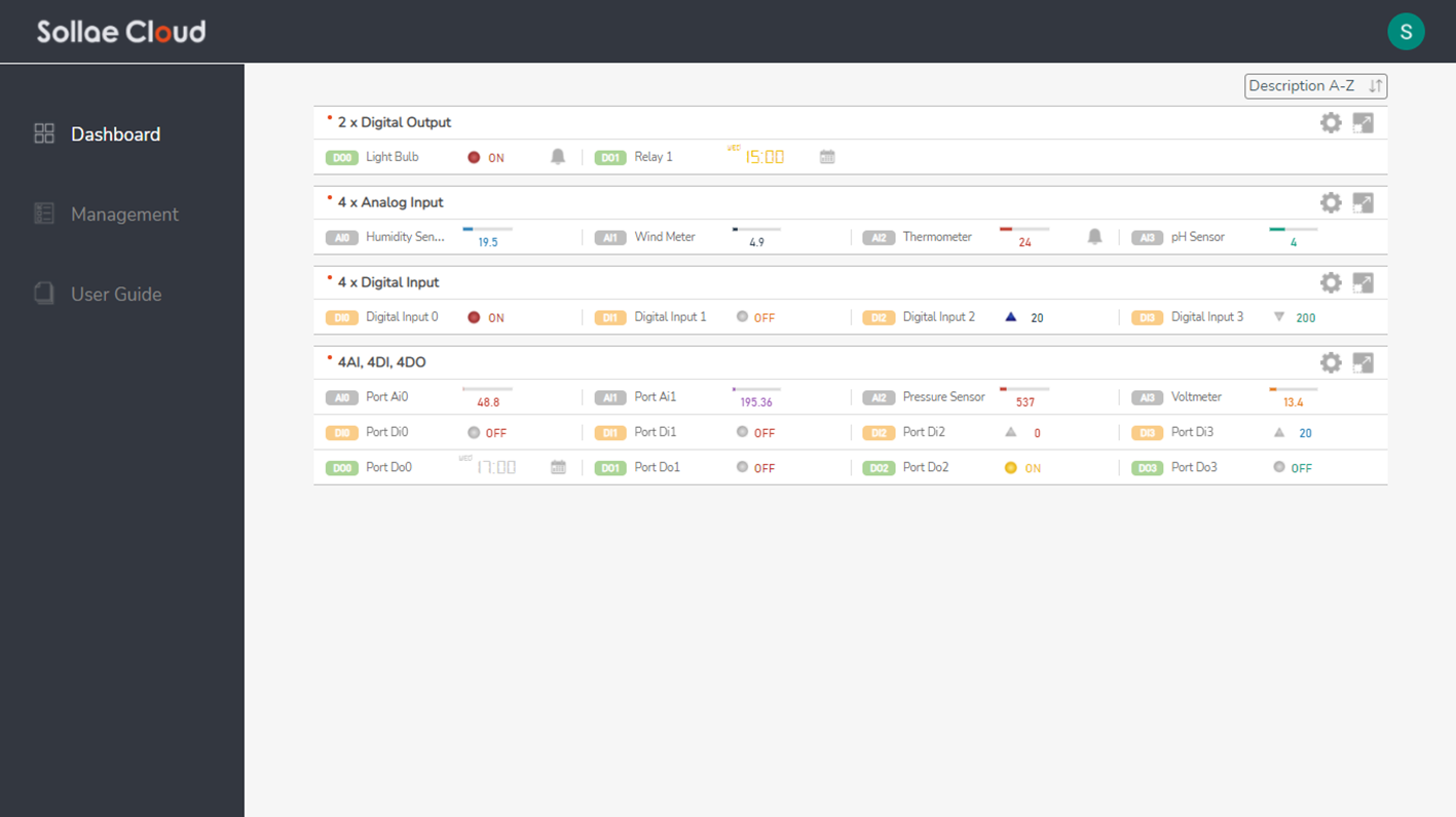
Desktop Dashboard Theme
Select the dashboard theme for desktop view. You can choose one among Normal View, Compact View, and Simple View.
Center Align: Set the alignment of the widgets in a device dashboard.
Mobile Dashboard Theme
Select the dashboard theme for mobile view. You can choose one among Normal View, Compact View, and Simple View.
Language
Choose your display language. Currently, Sollae Cloud supports English and Korean.
Set your working timezone. The operation of the scheduling and device data logging features relies on this. By default, UTC timezone (Coordinated Universal Time) is used.
Show Confirmation Dialog
Alarm Effects Dismissal: Show/hide the confirmation dialog when a user clicks on an alarm icon of a port widget to dismiss its existing alarms' effects. If unset, there will be no confirmation dialog as the alarm effects are dismissed immediately.
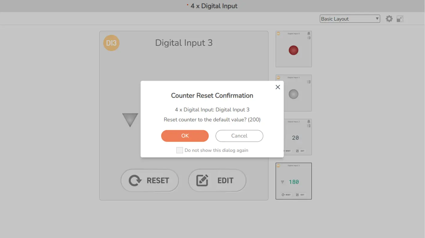
Counter Value Reset: Show/hide the confirmation dialog when a user clicks on a counter RESET button of a digital input widget. If unset, there will be no confirmation dialog as the command is sent immediately.
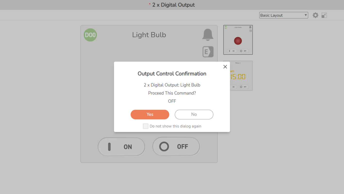
Output Command Control: Show/hide the confirmation dialog when a user clicks on a control button of a digital output widget. If unset, there will be no confirmation dialog as the command is sent immediately.
Toast Messages
Disable Notification Messages: A Notification message indicates a system notice or successful operations. By default, after showing up, the Notification messages automatically disappear in a few seconds. If set, no Notification message will show up.
Auto Close Warning Messages: A Warning message indicates an invalid user request. By default, after showing up, Warning messages need to be closed manually by users. If set, the Warning Messages will disappear automatically.
Auto Close Error Messages: An Error message indicates a system issue or failed operations. By default, after showing up, Error messages need to be closed manually by users. If set, the Error Messages will disappear automatically.
Quick-access Preferences
You can also view and change essential preferences from the top-right menu. Click on the user account icon to toggle this view.
All the preferences in Sollae Cloud web app (e.g. language, timezone, etc.) are only meant for Sollae Cloud, and completely independent with Google preferences.
Chart widget is only available for Normal View.
Chart widget is only available for Normal View.
Read more: Introduction to Sollae Studio
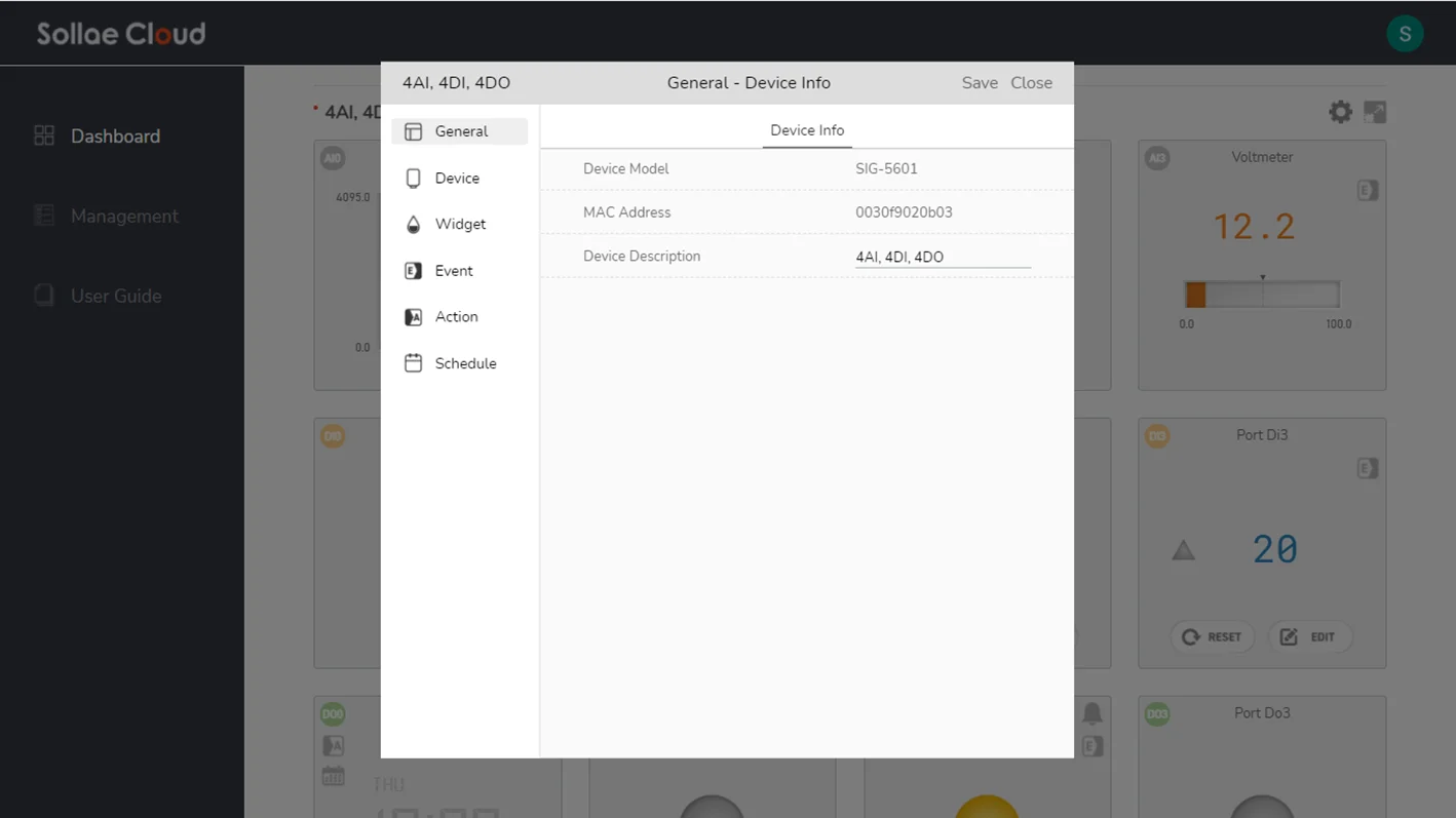
This page is used to configure an individual device and its ports. It can be accessed via Device Configuration button or setting shortcut buttons.
Setting via web app is only available for the devices that are being registered and connected to Sollae Cloud, so please make sure a device is connected before configuring its parameters.
Read more: Setting via Web App
In this section, we use the notations below to classify setting parameters:
Common parameter.
Available for Analog Input.
Available for Digital Input.
Available for Digital Output.
Supported Model
SIG-5431
SIG-5441
SIG-5451
SIG-5561
SIG-5601
Supported Model
SMG-5511
SMG-5521
In this document, we use the term HIGH/LOW to refer to the logic state. When you monitor the state of Sollae digital I/O devices via spFinder, you can see the state HIGH is indicated by value 1 and the state LOW is indicated by value 0.
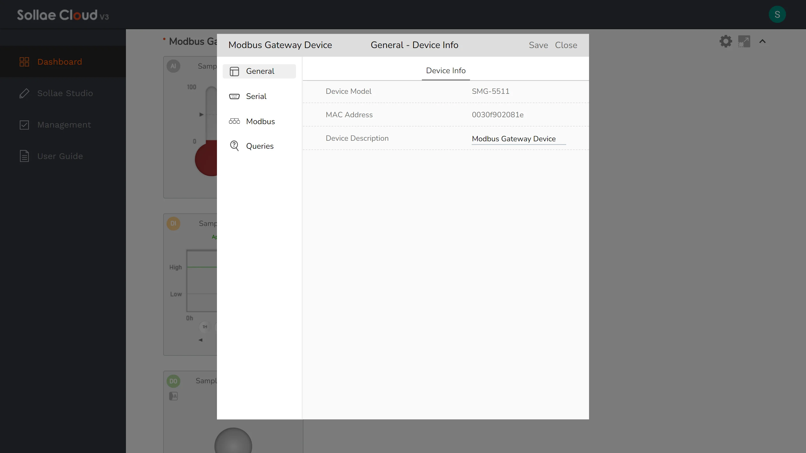
View and configure the common setting for a device.
Device Model: Display device model. This field is read-only.
MAC Address: Display device MAC Address. This field is read-only.
Device Description: Use to indicate the device within Sollae Cloud web app. If no description is available, the MAC address will be used. When a device is registered, it looks up the device-stored description that has been set on the device via spFinder, and uses this as the initial value. Any modifications afterward via web app are separate from the device-stored description.
Specify the working parameters of each port in a device. This feature is only available for the SIG models.
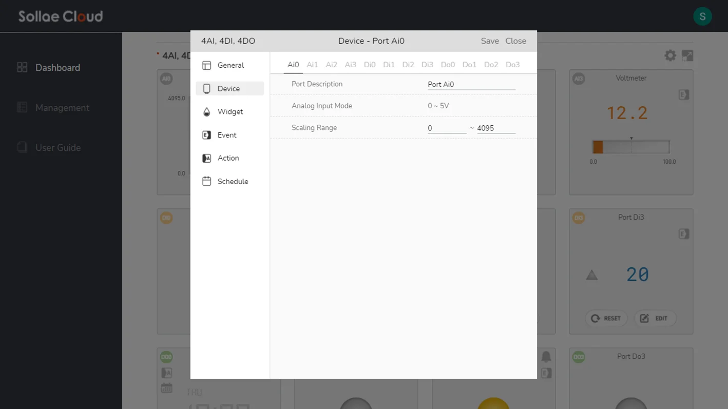


Port Description: Used to indicate an individual port in Sollae Cloud.
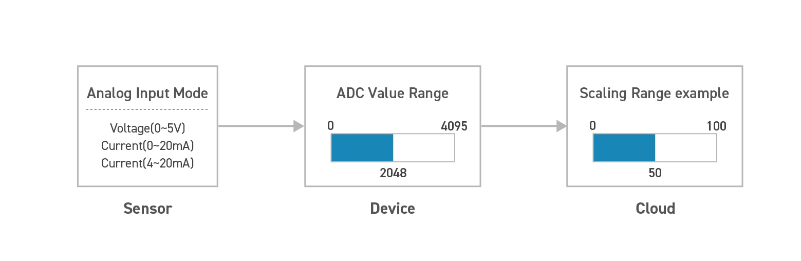
Analog Input Mode: Display the setting for the analog input mode of the port. For typical Sollae devices, there are three analog input modes available, including voltage (0 ~ 5V), current (4 ~ 20mA), or current (0 ~ 20mA).
Scaling Range: SCALING_VALUE = ADC_VALUE x ( SCALING_MAX - SCALING_MIN ) / 4095 + SCALING_MIN. Depending on the Analog Input Mode, the input signal is measured by its voltage or current, and then will result as an ADC value ranging from 0 to 4095 (12-bit ADC). For instance, if the Analog Input Mode is set as 0 ~ 5V, then a 0V input voltage will result as the ADC value 0, 5V input voltage will result as the ADC value 4095, and so on. In real applications, users may wish to transform the ADC value into a more practical one, and they can set up the Scaling Range for that purpose. The scaling function covers the general case in which sensors/analog equipment has a linear output. It rescales the data linearly based on the value range. As an example, if a temperature sensor outputs the highest value as 4095 at 100°C and the lowest one as 0 at 0°C, then it is useful to rescale the ADC value. The Scaling Range should be set as 0 ~ 100, as SCALING_MIN = 0 and SCALING_MAX = 100, so an ADC value 2048 will be mapped to: 2048 x (100 - 0) / 4095 + 0 = 50(°C). In Sollae Cloud, this scaled value, instead of the ADC value, is used to represent the analog value of the port. The default value is 0 ~ 4095. If you wish to just use the ADC value, leave the Scaling Range as 0 ~ 4095.
Valid Time (ms): Debounce time for the input port. In order for the input signal to be considered as a valid signal, it must last longer than this period. The default value is 100 (unit: millisecond).
Counter Type: Set the counter for the number of rising/falling edges, or both, on the input signal. The default value is Rise.
Counter Direction: Count up or count down. The default value is Count Up.
Default Counter Value: The value at which the digital input port starts to count after the device boots up. The default value is 0. In case you set the Counter Direction to Count Down, you also need to set the Default Counter Value to non-zero.
Fail-safe Mode: Display the setting for the Fail-safe mode of the port. If enabled, when the MQTT connection with Sollae Cloud is lost, the output port is set to LOW. It is expected to have a delay before a connection loss is detected, as the network timeout needs to be passed. It may take around a minute for Sollae devices to enter the Fail-safe mode after the connection loss happens.
Some setting parameters in this category are locally stored on Sollae device memory. If any of those parameters are changed, the device's MQTT connection is required to be restarted. This means the said device will be disconnected from the cloud for a while during the setting update process. Also, for each digital input port, its counter value will be reset to the Default Counter Value. Please consider this to avoid possible issues or disruptions within your system.
Besides, due to the device stability concern, Analog Input Mode and Fail-safe Mode are made to be read-only on the web app. These parameters can be configured using spFinder.
Besides, due to the device stability concern, Analog Input Mode and Fail-safe Mode are made to be read-only on the web app. These parameters can be configured using spFinder.
Customize the display UI of a device.
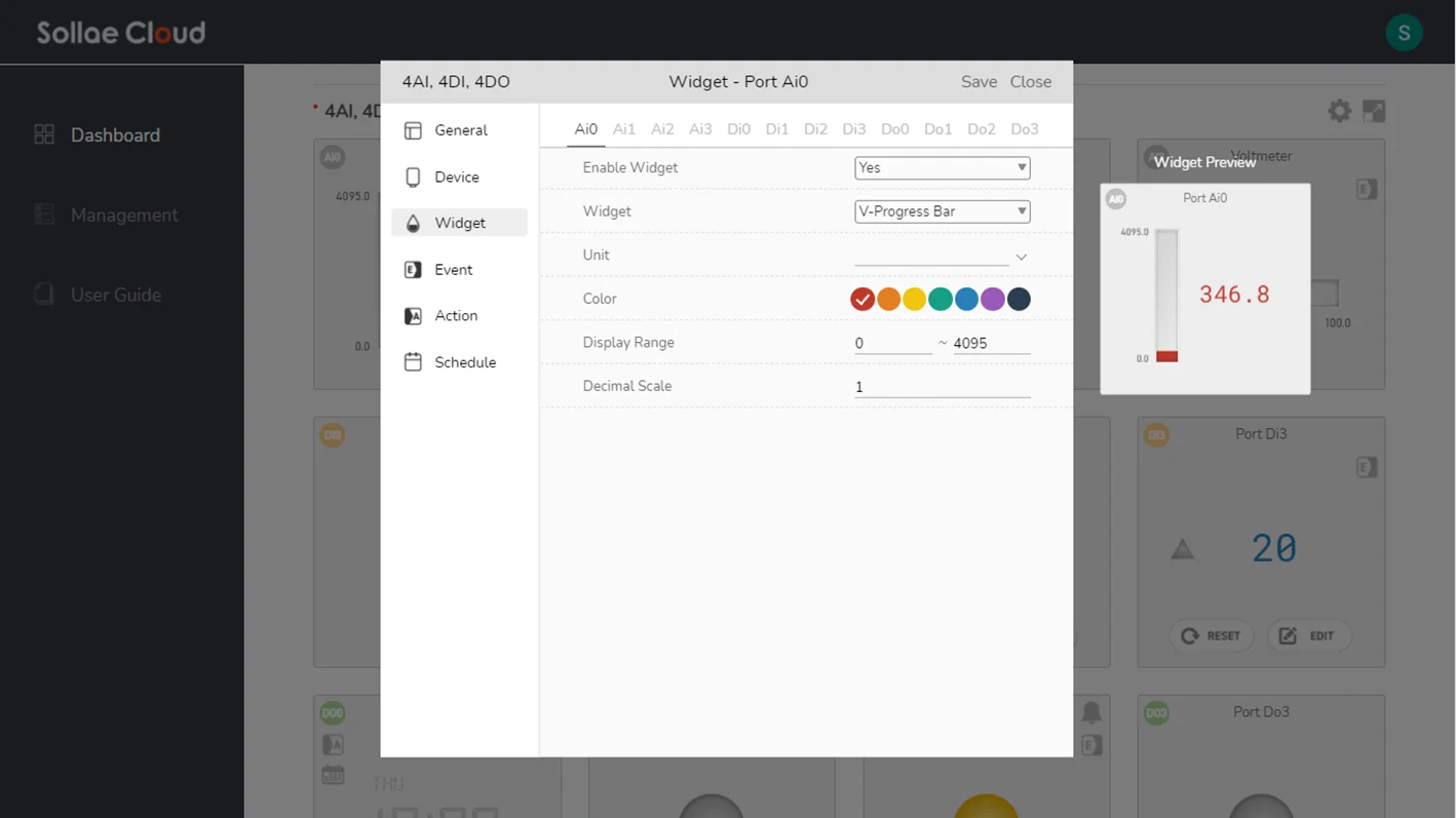
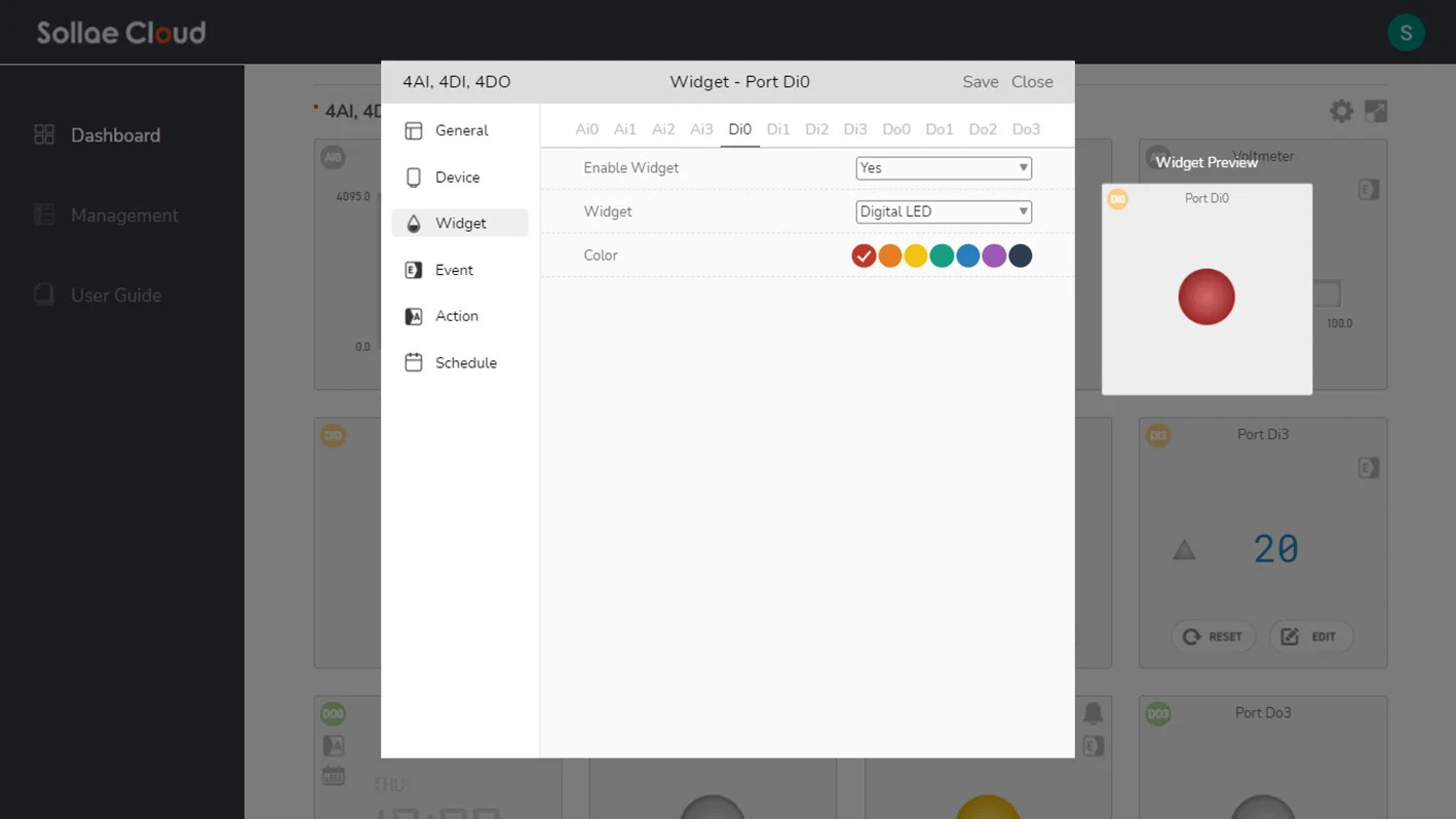
Enable Widget: Show/hide visualization of a port.
Widget: Change the visualization style with our provided widgets.
Color: Select the widget color style.
Unit: Set the displayed unit on a port widget.
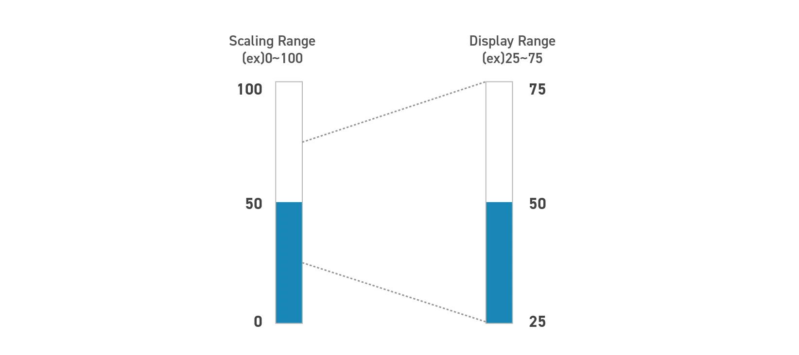
Display Range: Set the display range for data visualization. The default value is 0 ~ 4095. In many situations, the meaningful range is much narrower than the possible scope of the analog value. For example, the possible value obtained by a sensor is from 0 to 100 (Scaling Range is set as 0 ~ 100), however, in the real application, it almost only returns the value from 25 to 75. In this case, the Display Range can be set as 25 ~ 75 for better focusing.
Decimal Scale: Set the display format of the analog value as how many digits after the decimal point should be displayed. If set to 0, any floating-point value will be rounded to an integer.
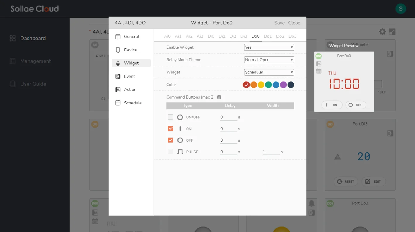
Command Buttons: Select the buttons for the digital output widget. These buttons are used to send the control command to digital output ports via the web app. For each port, you can enable none, one or two buttons at maximum. The command type can be ON (turn on), OFF (turn off), ON/OFF (toggle) or PULSE (generate a pulse). If the delay is set to 0, the output will be generated immediately once the Sollae device receives the command. The valid range for Delay is 0 ~ 1800, and for Pulse Width is 1 ~ 1800 (unit: second). You can refer to the Multi-controlling for more details.
The widget preview inside this window is only for UI demonstration. The state and value displayed in the widget preview are not the real-time data of the device.
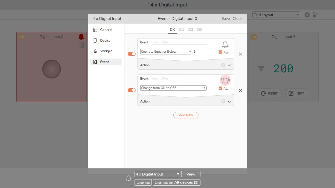
Create a user-defined event by specifying the operating condition on a port. In Sollae Cloud, an event is termed to occur when its defined condition is met. During device operation, each time the condition of an event turns from unmet to met, it will be counted as one occurrence of the said event. When the condition of an event turns from met to unmet, we say that the event has ceased.
Available events
When the analog value falls to a value equal to or lower than the Set Value
When the analog value rises to a value equal to or larger than the Set Value
When the input state changes from ON to OFF
When the input state changes from OFF to ON
When the counter value turns to a value equal to or lower than the Set Value
When the counter value turns to a value equal to or larger than the Set Value
When the output state changes from ON to OFF
When the output state changes from OFF to ON

Configuration parameters
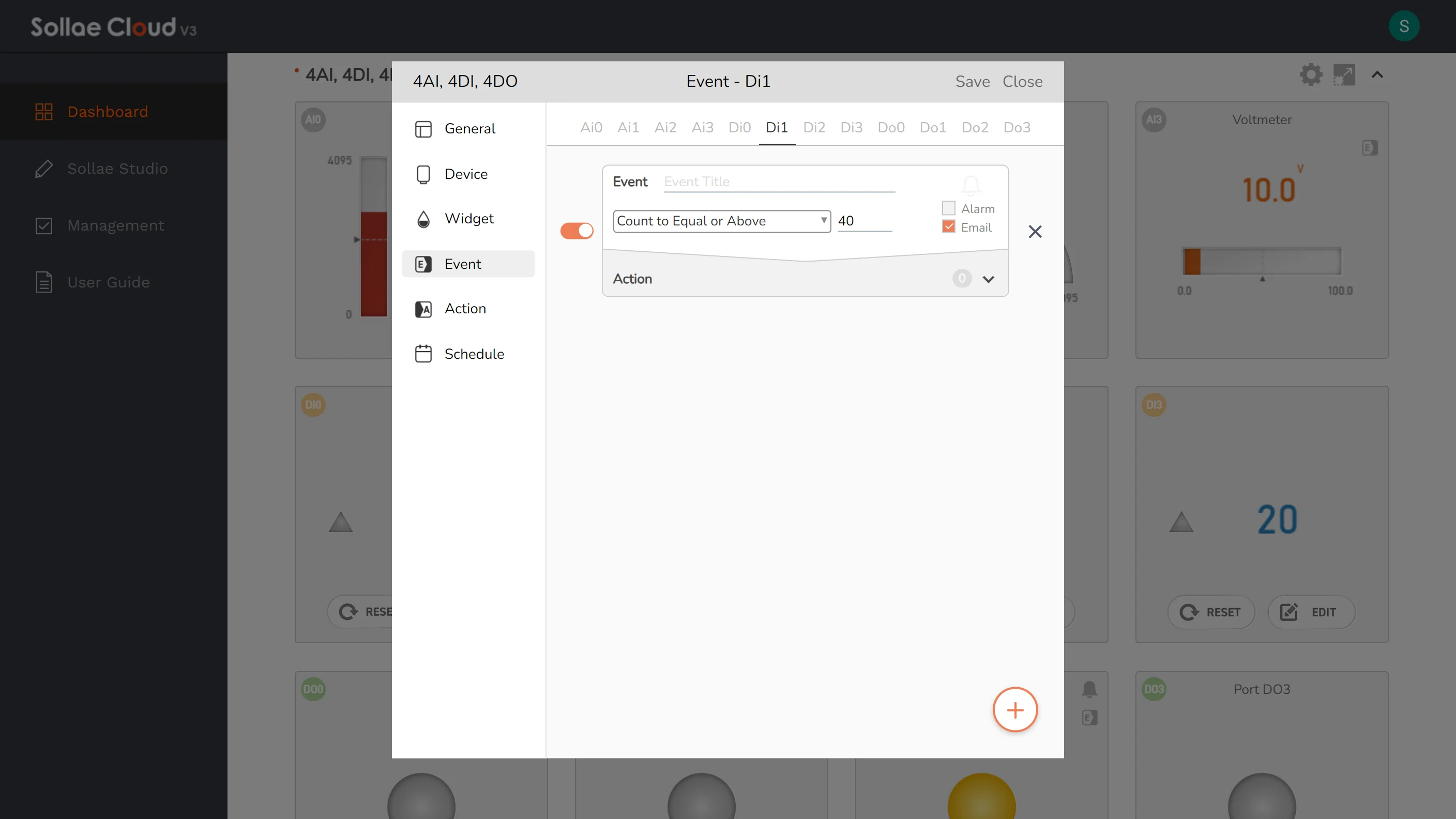
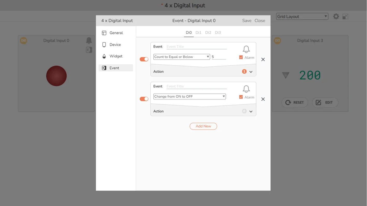
Event Enable Switch: Enable or disable the event. Only available for the existing events that have been saved.
Event Condition: Specify the port operating condition for an event.
Event Title: Your brief description of the event.
Alarm Indicator: If Alarm Enable Option is set, the Alarm Indicator will be blinked when this event occurs. You can click on it to stop the alarm effect.
Alarm Enable Option: Set/unset alarm notification for an event. If set, there will be alarm effects every time this event occurs.
Email Enable Option: Set/unset email notification for an event. If set, an email will be sent to the account you logged in, every time this event occurs.
Event Remove Button: Delete the event.
Action Panel: Click to expand/collapse the Action configuration menu. Also, the number of actions that will be triggered when this event occurs is displayed here.
Action List: Show the list of configured actions that will be triggered when this event occurs. You can edit/remove the existing actions.
Add Action Button: Define new action that will be triggered when this event occurs.
Add New Button: Create a new event on the port.
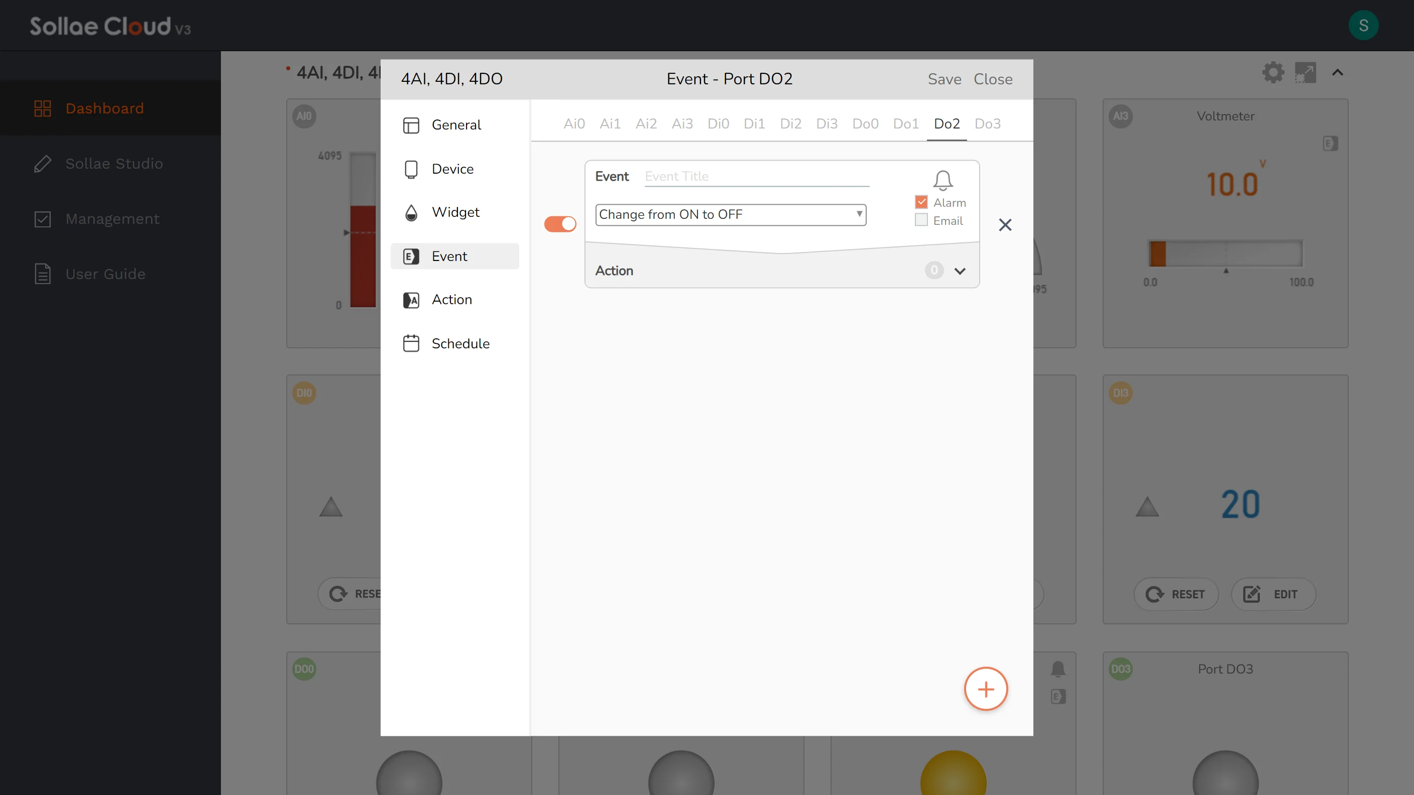
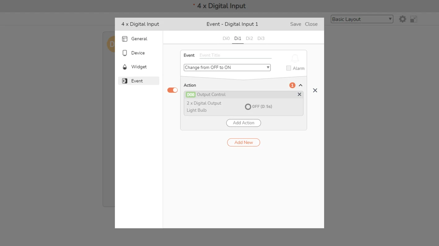
Click Add New to create a new event.
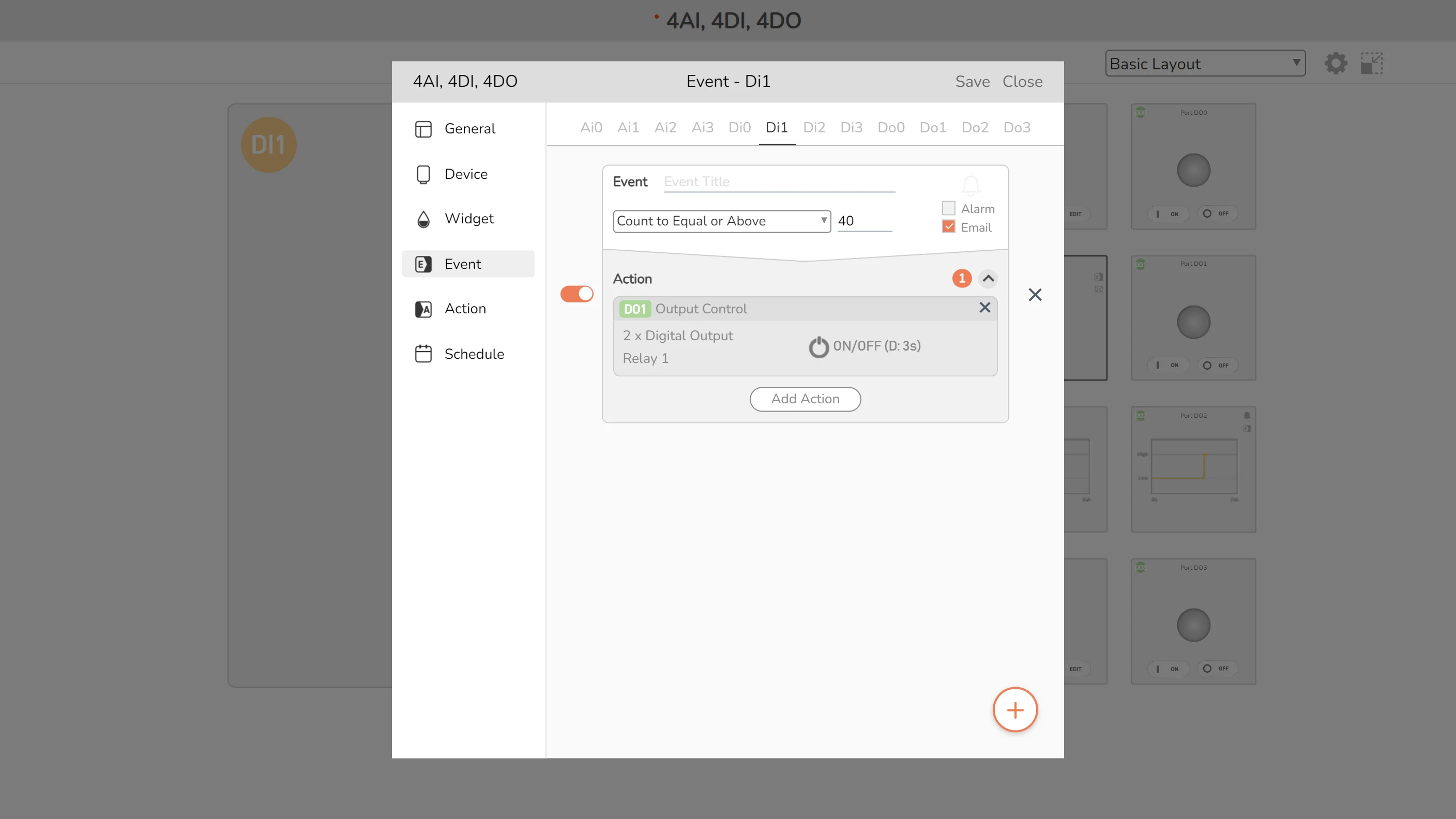
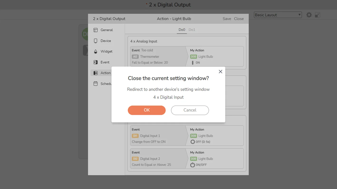
In the Event configuration window, you can define the event parameters, edit/remove an event or enable/disable existing ones. Remember to save the setting to Sollae Cloud to apply the changes you made.
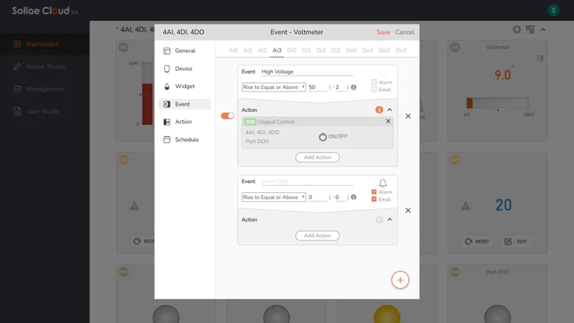
If you wish to control output ports when an event occurs, you can set the actions to be triggered. Click on the Action Panel to toggle the action configuration window.
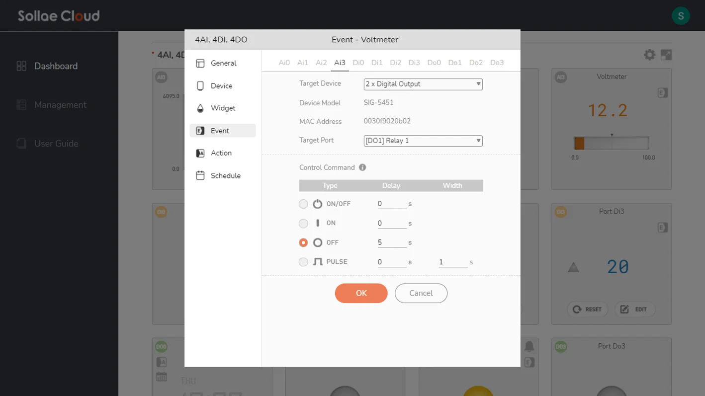
Click Add Action to create a new action for an event. A window to configure a new action will be popped up. You can configure the output digital port/device as the target, and set the control command parameters for the action. The valid range for Delay is 0 ~ 1800, and for Pulse Width is 1 ~ 1800 (unit: second).
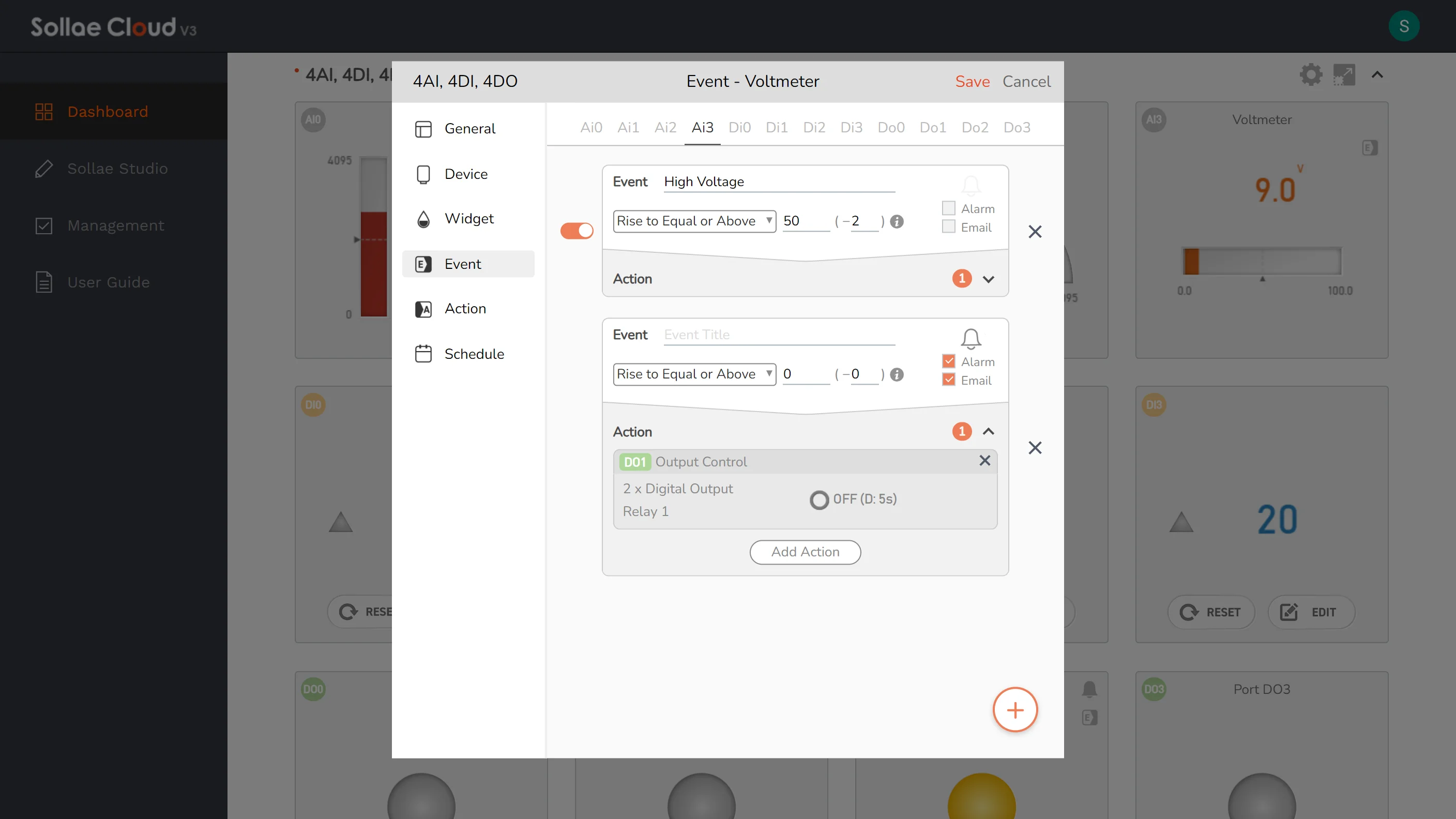
You can add/edit/remove actions in an existing event or a newly created one. All the actions set for an event will be executed when the event occurs.
While most of the Event Condition parameters are self-explanatory, it is worth mentioning that there is an additional parameter for the analog input port's event, called Tolerance. In real applications, analog input value tends to vary continuously, thus it may fluctuate around the Set Value of an event multiple times, causing an unexpected number of event's occurrences. Setting the Tolerance parameter may help to deter this chattering effect.
When the event is conditioned as the Analog Value rises above a Set Value: An event is considered to have occurred if the Analog Value rises from lower than, to equal to or greater than, the Set Value. Once an event occurs, its current occurrence ends, or in other words, it is ceased, only if the Analog Value falls to lower than Set Value(- Tolerance).
When the event is conditioned as the Analog Value falls below a Set Value: An event is considered to have occurred if the Analog Value falls from greater than, to equal to or lower than, the Set Value. Once an event occurs, its current occurrence ends, or in other words, it is ceased, only if the Analog Value rises to greater than Set Value(+ Tolerance).
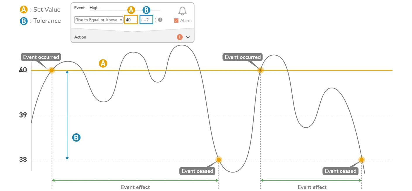
An event will be re-evaluated each time the data is updated. By default, the analog data is updated every 5 seconds.
The Analog Value always lies within the Scaling Range. Depending on the configuration, an event will be ceased only if the Analog Value turns to lower than Set Value(- Tolerance), or greater than Set Value(+ Tolerance). To make a valid event for analog ports, the Scaling Range's boundary needs to be taken into account when configuring the Set Value and Tolerance.
Currently, the supported actions are to control your Sollae devices' relays, thus actions will be unavailable if you do not have any Sollae digital output device registered under your account.
Currently, the supported actions are to control your Sollae devices' relays, thus actions will be unavailable if you do not have any Sollae digital output device registered under your account.
Read more: User-defined Event
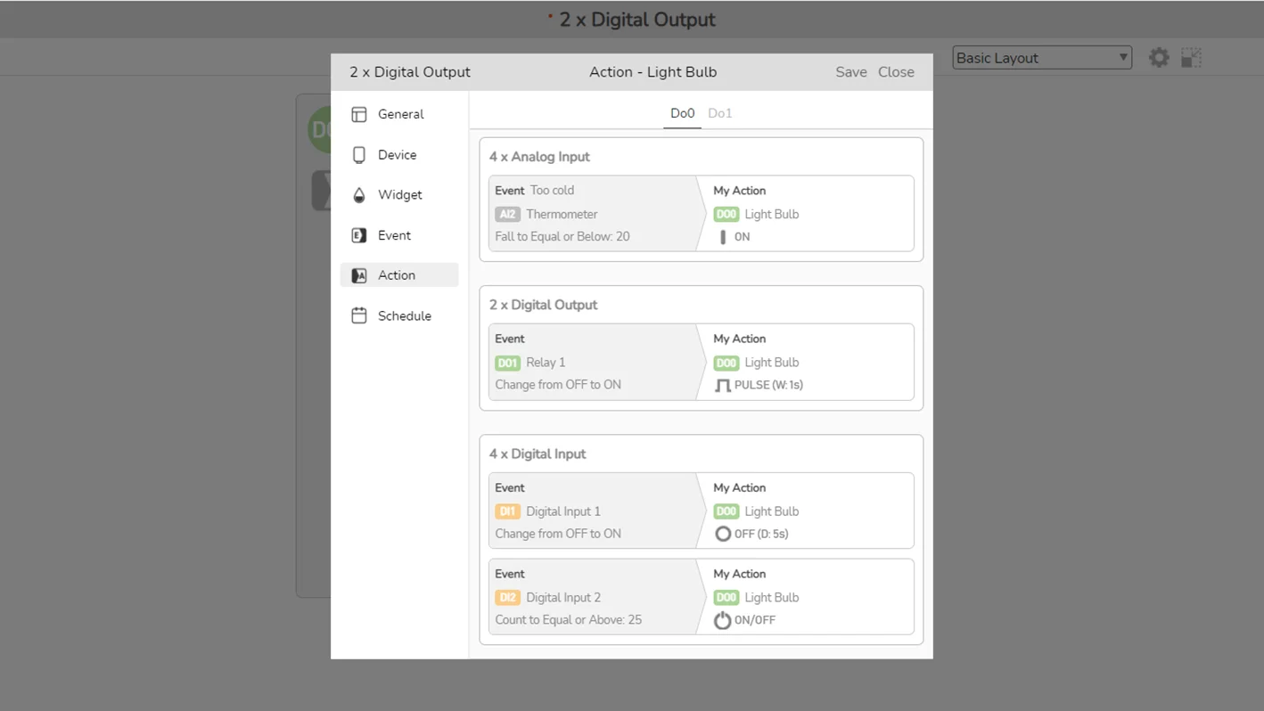
View the list of existing events and actions they may trigger on a port. This feature is only available for the digital output ports.
The Action page is for viewing only. The items, which include the descriptions for trigger event/target action, are displayed and grouped by trigger devices.
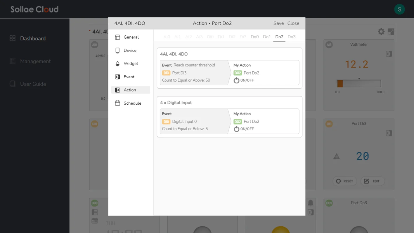
Each item listed here also provides shortcut access to the configuration page of the trigger event.
To edit/remove an existing action, you can click on the displayed item to move to the Event page accordingly.
In order to configure an event-based action for an output port, you need to determine which event you wish to be the trigger. The trigger event can belong to any of your registered devices. Visit the Event configuration page of the trigger device to set up the action.
Read more: Event-based Action
Set up a schedule for scheduled automation. This feature is only available for the digital output ports on the SIG models.
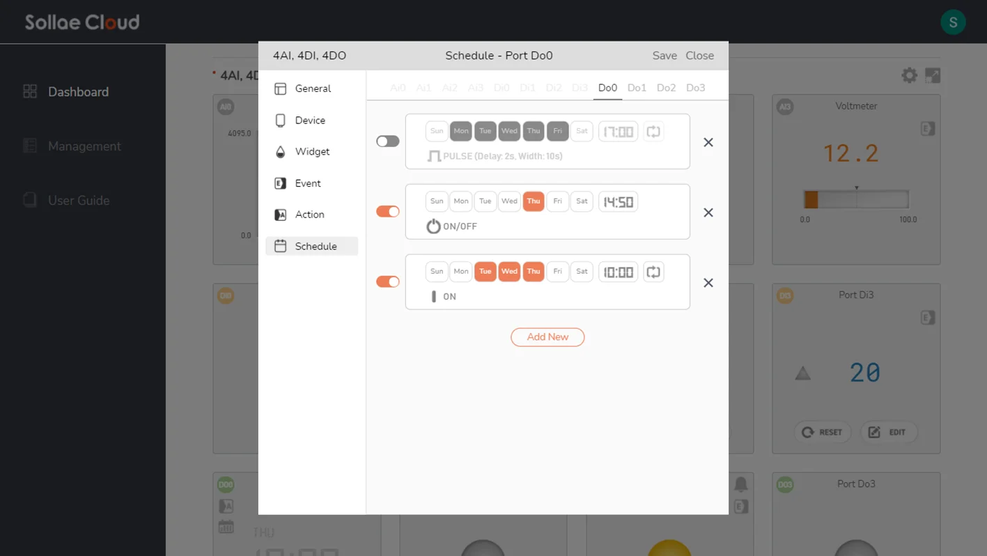
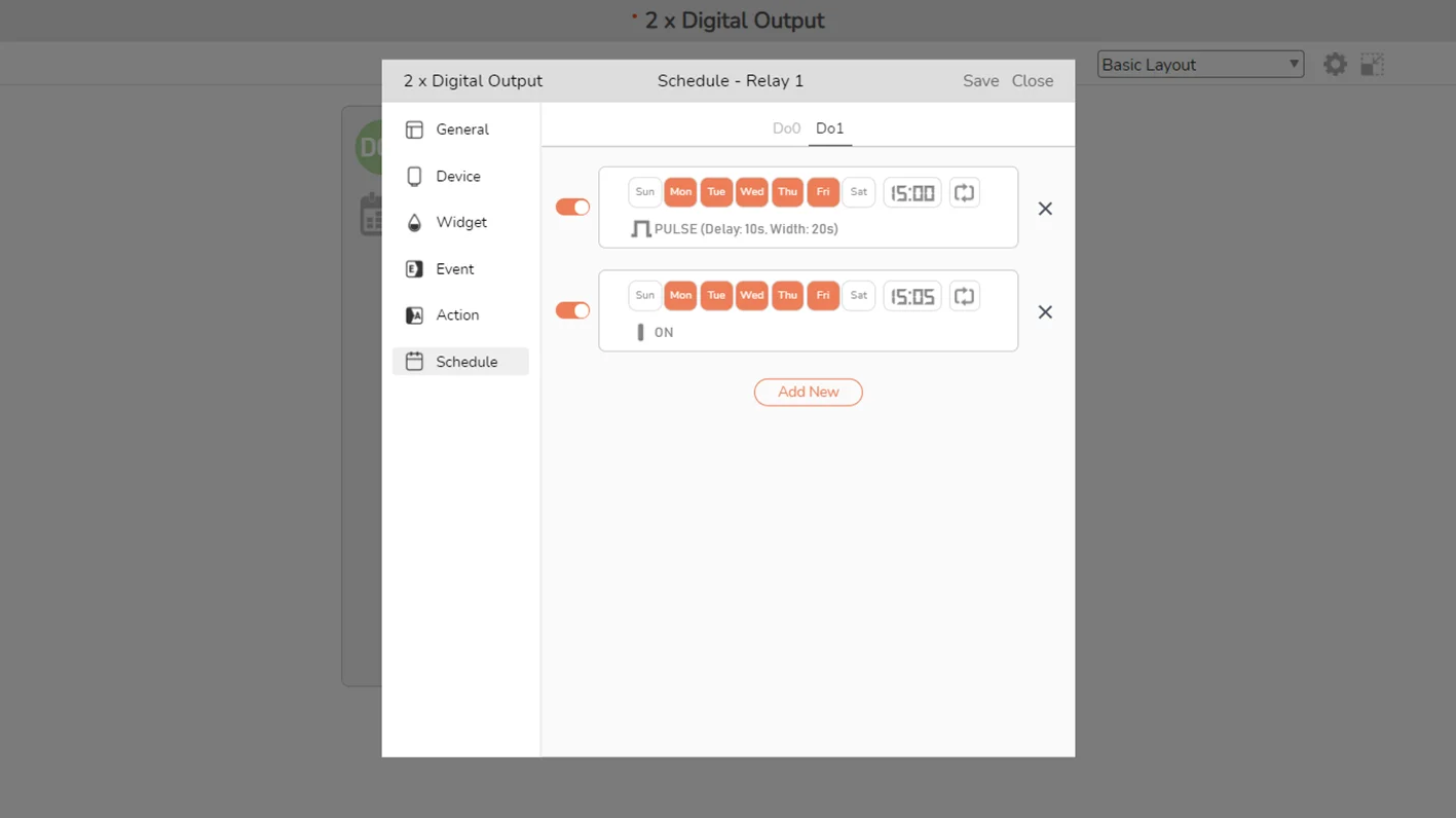
Click Add New to create a new schedule. A window to configure a new schedule will be popped up.
Configuration parameters
Day of the Week: Set the days of the week for the schedule.
Time (hour, minute): Set the time for the schedule.
Repeat Weekly Option: If set, the schedule will be executed weekly. If unset, it will only execute once, and you can choose only one day of the week for the schedule.
Control Command: Specify the command you want, among turning on/off, toggle or generating a pulse on the output. The valid range for Delay is 0 ~ 1800, and for Pulse Width is 1 ~ 1800 (unit: second).
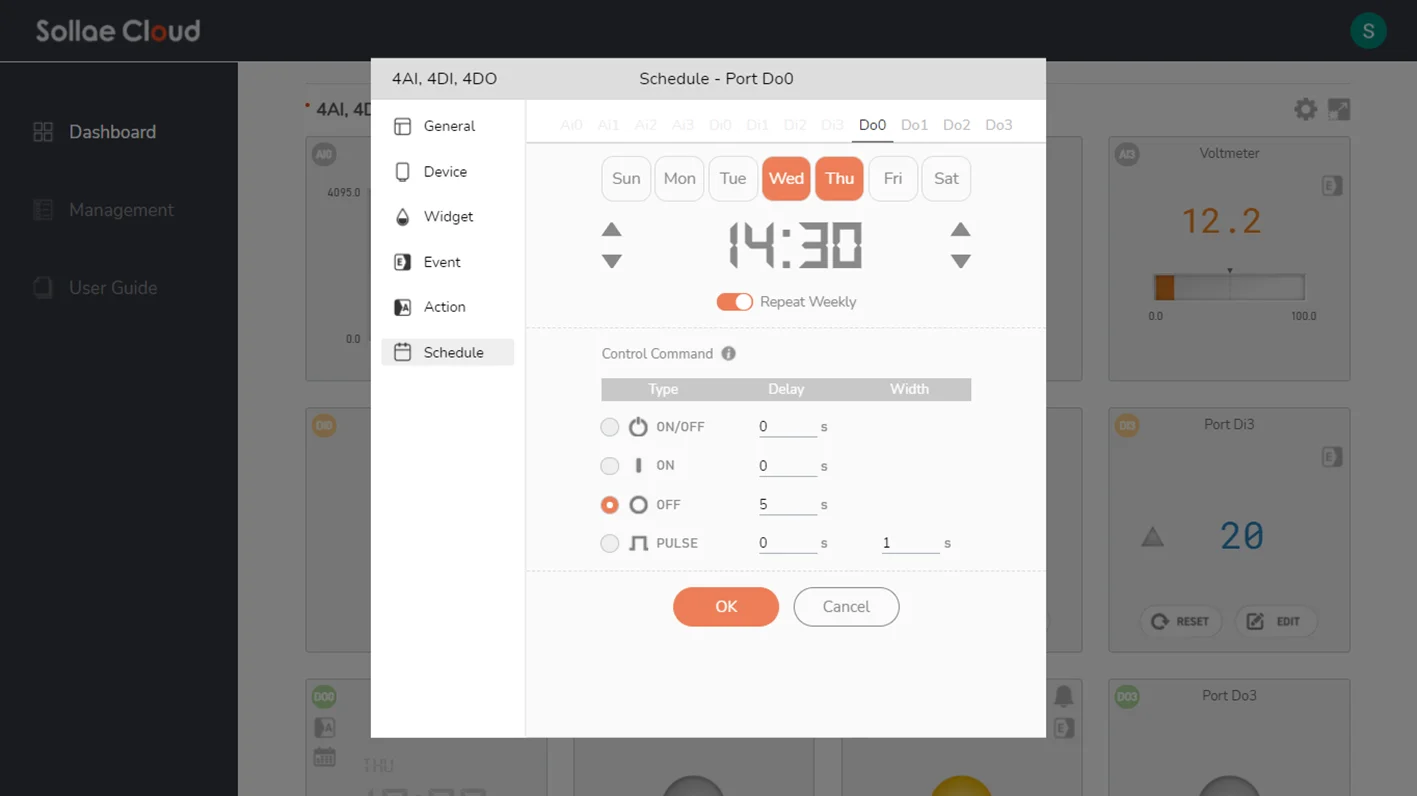
Click OK to proceed. Click Cancel to discard.
In the Schedule configuration window, you can remove a schedule or enable/disable existing ones. If you want to edit an existing schedule, just click on it to open the configuration window. Remember to save the setting to Sollae Cloud to apply the changes you made.
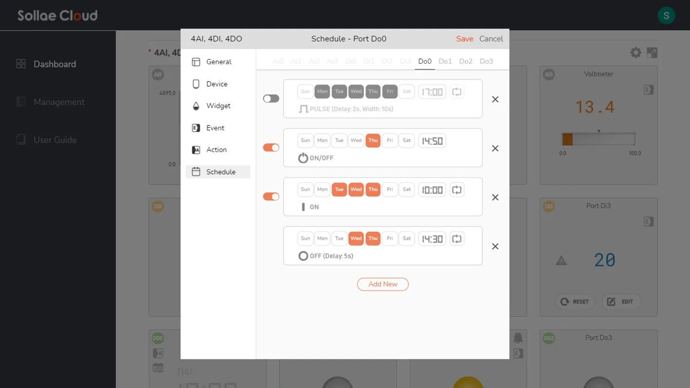
The operation of schedules uses Sollae Cloud's timezone. Remember to set the working timezone for Sollae Cloud in advance.
It is advisable to avoid making different schedules that have time overlap during their executions. If you set several schedules to take place at a time, then the later-set schedules' execution will override the previous ones, and that may cause unexpected behaviors for your application. You can refer to the Multi-controlling for more details.
On mobile browsers, you can enjoy major features similar to the desktop version. Note that, currently, the sound effect for Alarm is not supported on mobile browsers. To fully experience all functions of Sollae Cloud Web application, it is preferred to access from desktop browsers.
On mobile browsers, you can enjoy major features similar to the desktop version. Note that, currently, the sound effect for Alarm is not supported on mobile browsers. To fully experience all functions of Sollae Cloud Web application, it is preferred to access from desktop browsers.
Read more: Scheduling Function
Set up serial configurations. This feature is only available for the SMG models.
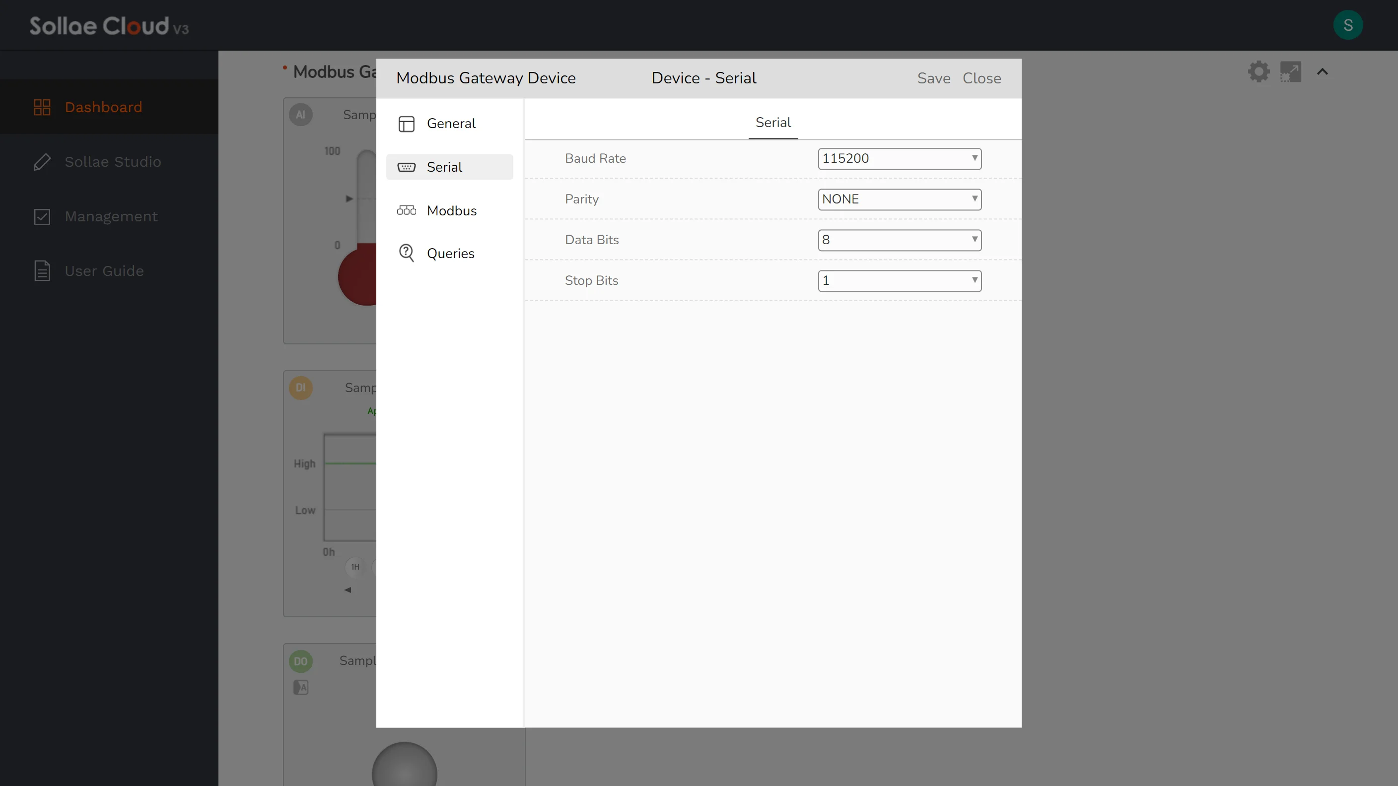
Baud Rate: Select a baud rate for the serial port from the supported list: 1,200bps, 2,400bps, 4,800bps, 9,600bps, 19,200bps, 38,400bps, 57,600bps, 115,200bps, 230,400bps. The default value is 9,600bps.
Parity: None, Even, Odd, Mark or Space. The default value is None.
Data Bits: Choose between 8 or 7. The default value is 8.
Stop Bits: Choose between 1 or 2. The default value is 1.
Set up Modbus configurations. This feature is only available for the SMG models.
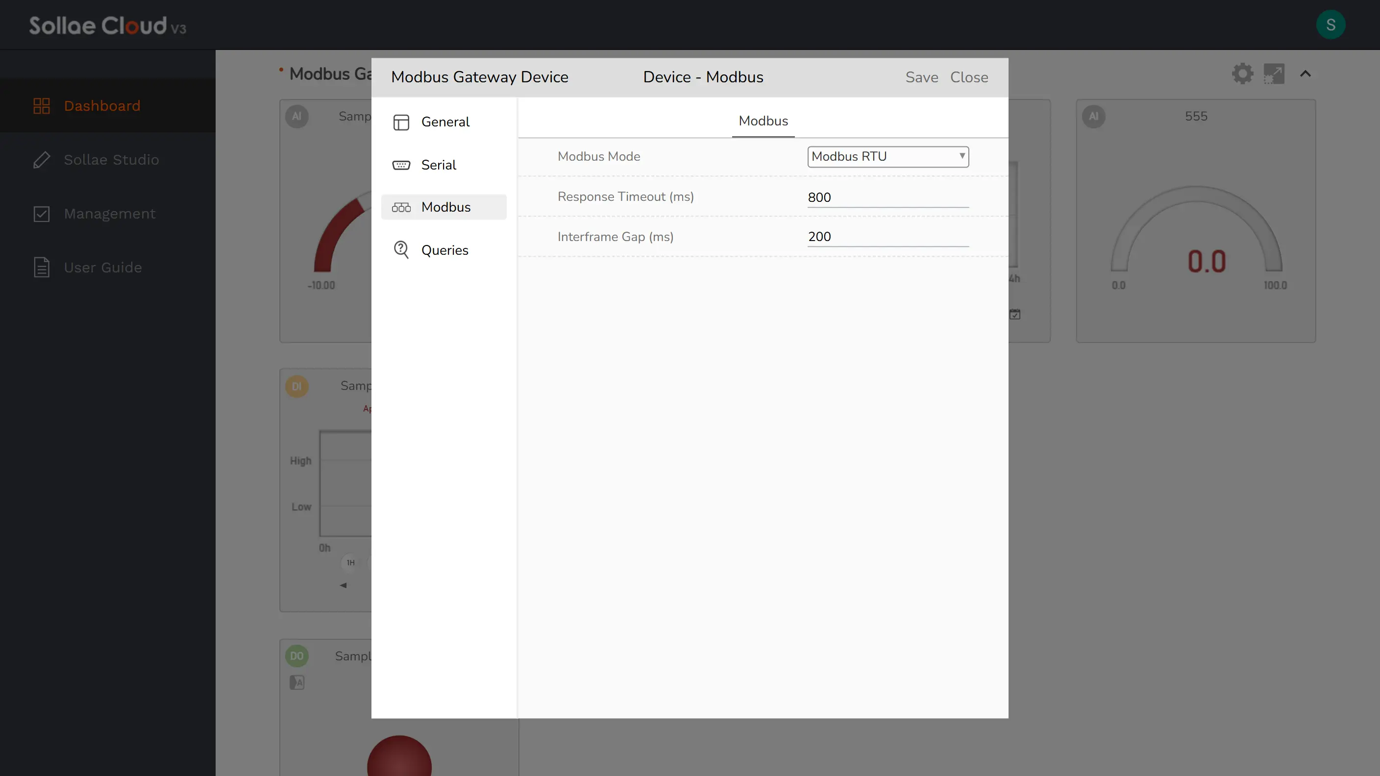
Modbus Mode: Select the communication protocol for the serial line. It should be configured according to the protocol of the connected serial device. The default value is Modbus RTU.
Response Timeout: Set the response timeout for a Modbus query. The unit is millisecond. It can be set to a number between 200 and 3000, and the default value is 500.
Interframe Gap: Set a delay between consecutive Modbus queries. The unit is millisecond. It can be set to a number between 0 and 5000. Note that, even if set to 0, the actual delay may be around from 13ms to 22ms due to internal processing. If you are not seeing this setting parameter, please upgrade your SMG devices to the latest firmware.
Set up Query configurations. This feature is only available for the SMG models. A query is established based on a Modbus request. Depending on the configured parameters, it will function similarly to an Analog Input, Digital Input, or Digital Output port on the Sollae IoT Gateway for Cloud. It processes data from the Modbus response and displays it on the web via a Dashboard widget or Sollae Studio.
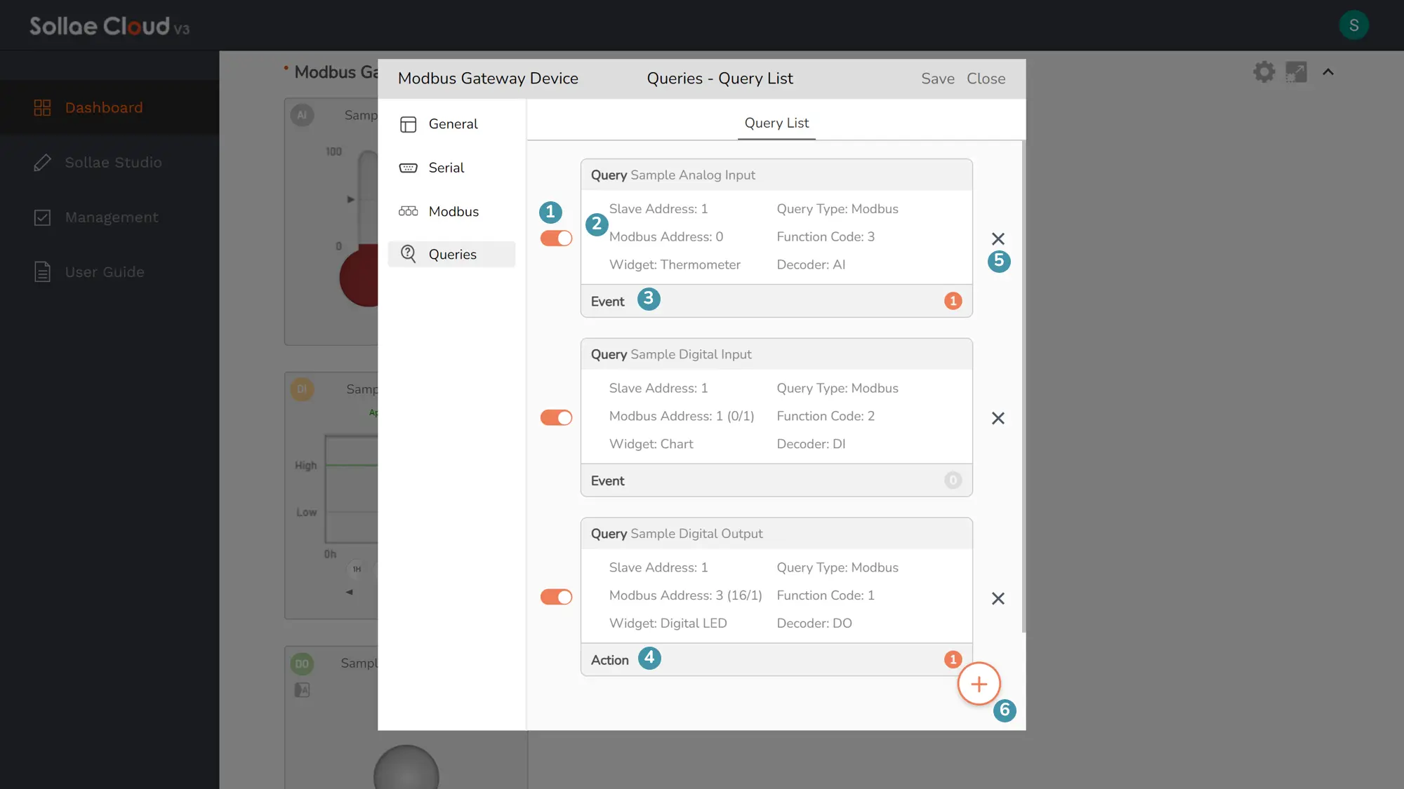
Components
Query Enable Switch: Enable or disable the query. Only available for the existing queries that have been saved.
Query Information Panel: A brief description of the query is displayed. Click to view and update the Address and UI parameters of this query.
Event Panel: Click to view and update the events set on this query. The total number of existing events set for the query is shown on the left. This panel is accessible only for queries saved as Analog Input or Digital Input.
Action Panel: Click to view the action list set for this query. The total number of existing actions targeted to the query is shown on the left. This panel is accessible only for queries saved as Digital Output.
Query Remove Button: Delete the query.
Add New Button: Create a new Modbus query.
Click Add New to create a new query. A window to configure a new query will be popped up.
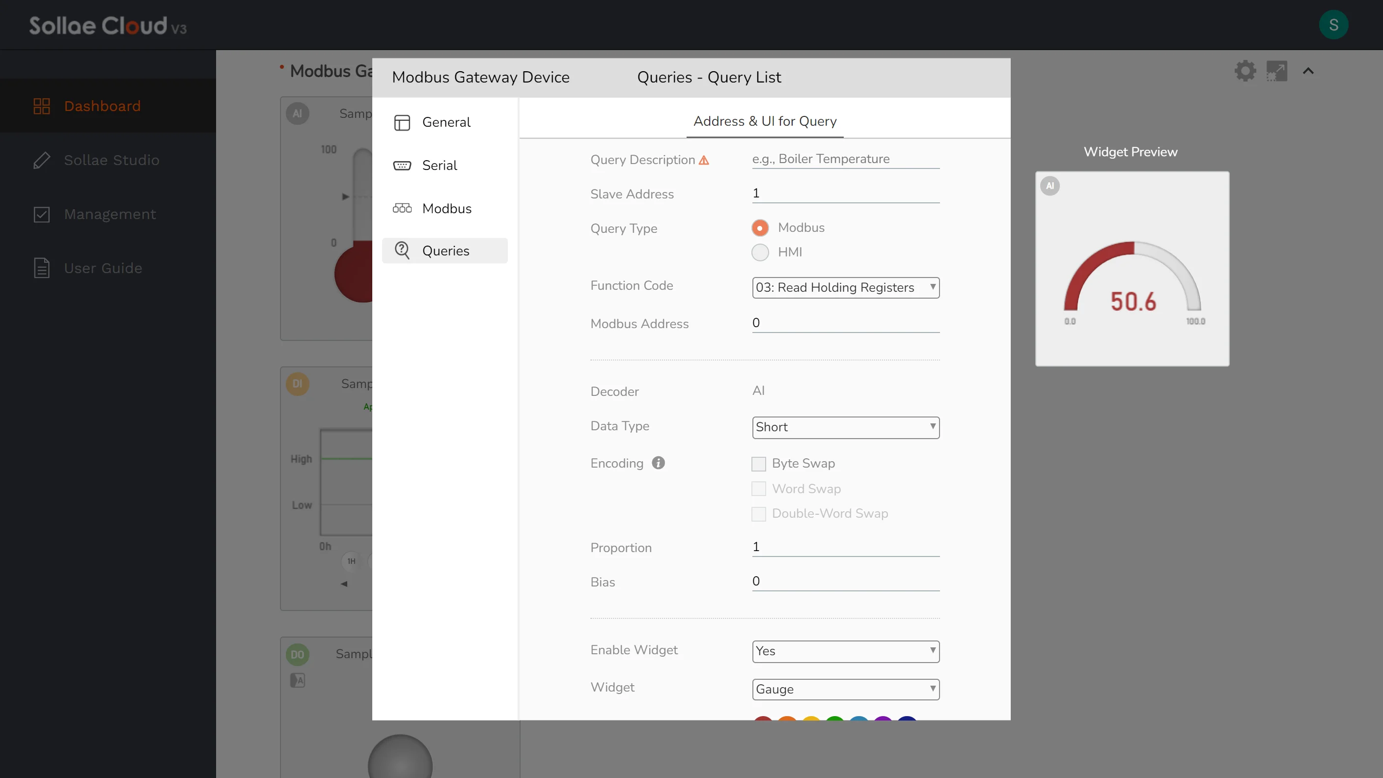
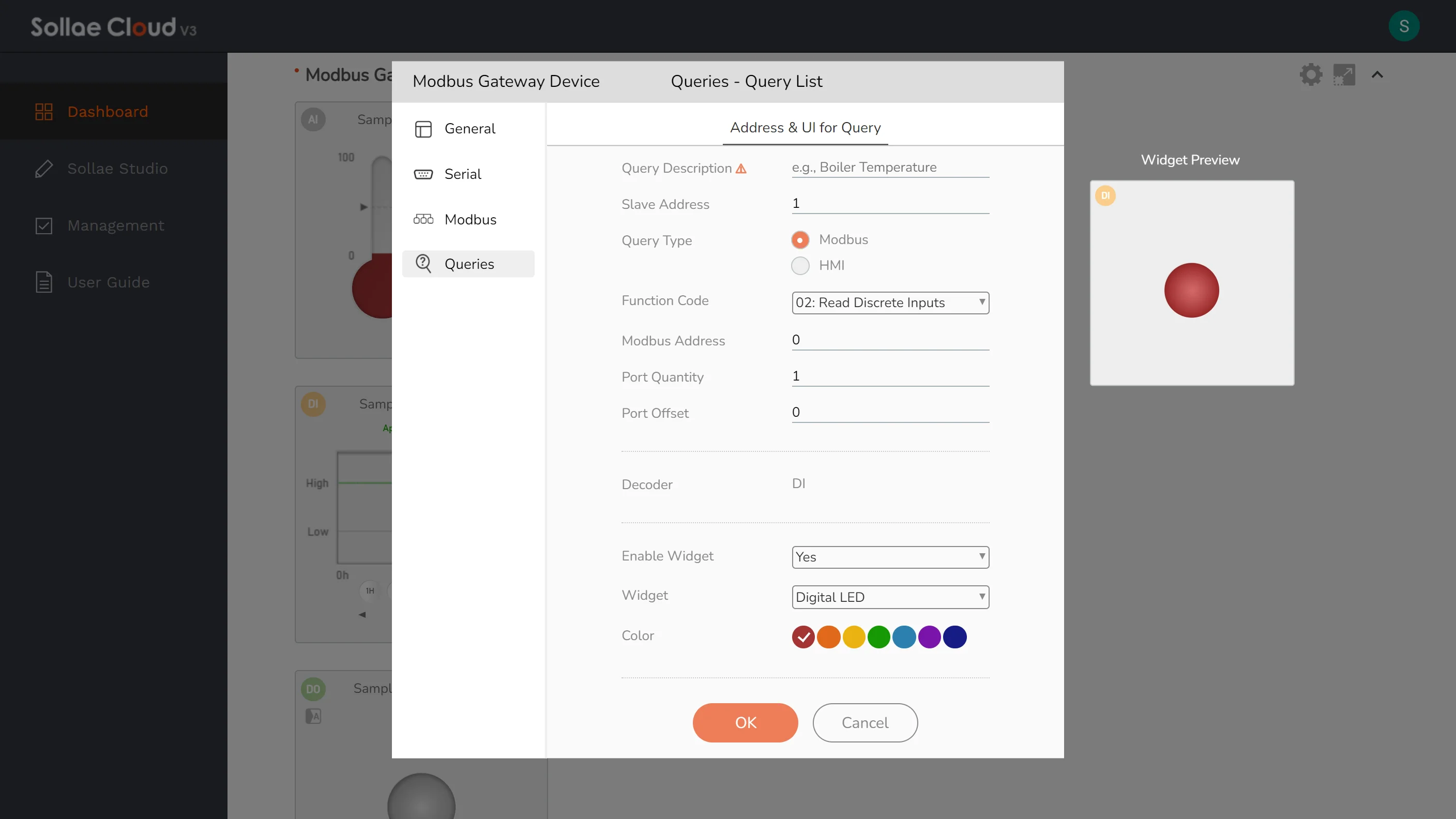
Configuration parameters
Query Description: Used to identify an individual query in Sollae Cloud. It is recommended to provide a descriptive name for better human readability. This field is required.
Modbus Request Settings: For a more detailed description of Modbus addressing, please refer to Modbus vs. HMI Addresses.
Slave Address: Set the slave address used for serial line Modbus communication (0 to 247). The default value is 1.
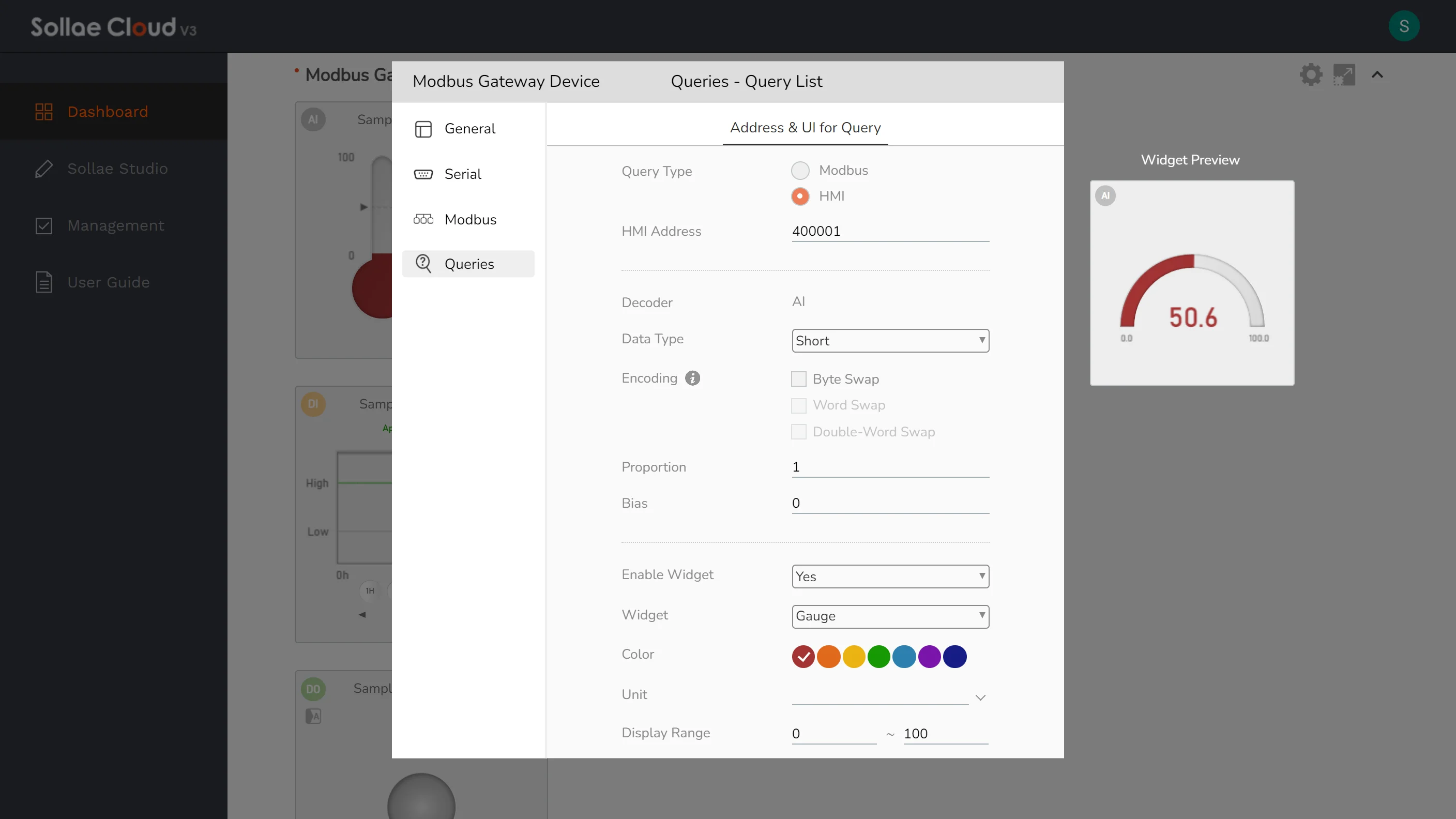
Query Type: Select between Modbus type and HMI type. For the Modbus type, users have to configure the Function Code and Modbus Address. For the HMI type, users have to enter the HMI address instead, as Function Code and Modbus Address will be inferred in the background. The default value is Modbus. This setting can not be changed once saved.
Function Code: Choose the Modbus function code from the four supported: Read Coils (01), Read Discrete Inputs (02), Read Holding Registers (03), and Read Input Registers (04). If configured with Read Coils, a query can work as a Digital Output. If configured with Read Discrete Inputs, it can work as a Digital Input. If configured with Read Holding Registers or Read Input Registers, it can work as an Analog Input. If you have set any events/actions attached to a query, you may not be able to change its function code. For example, if you have set a query with Read Holding Registers, and you registered some Analog Input events on it, then you cannot change the function code to Read Coils or Read Discrete Inputs, unless you remove all the attached events. Note that, any items on Sollae Studio tagged to a query may cease to work if the function code is changed.
Modbus Address: Set up the Modbus address of the device.
HMI Address: Specify the HMI Address of the device. Note that, currently, SMG models only support four function codes: Read Coils (01), Read Discrete Inputs (02), Read Holding Registers (03), and Read Input Registers (04). Only the HMI Address corresponding to the supported function codes can be used. This setting can not be changed once saved.
Port Quantity: Specify the number of digital I/O ports for this Modbus request.
Port Offset: Specify the offset of the digital I/O port for this query. The offset should range from 0 to Port Quantity - 1.
Modbus Response Settings:
Decoder: Define the query as Analog Input, Digital Input, or Digital Output, based on Modbus request settings. This field is read-only.
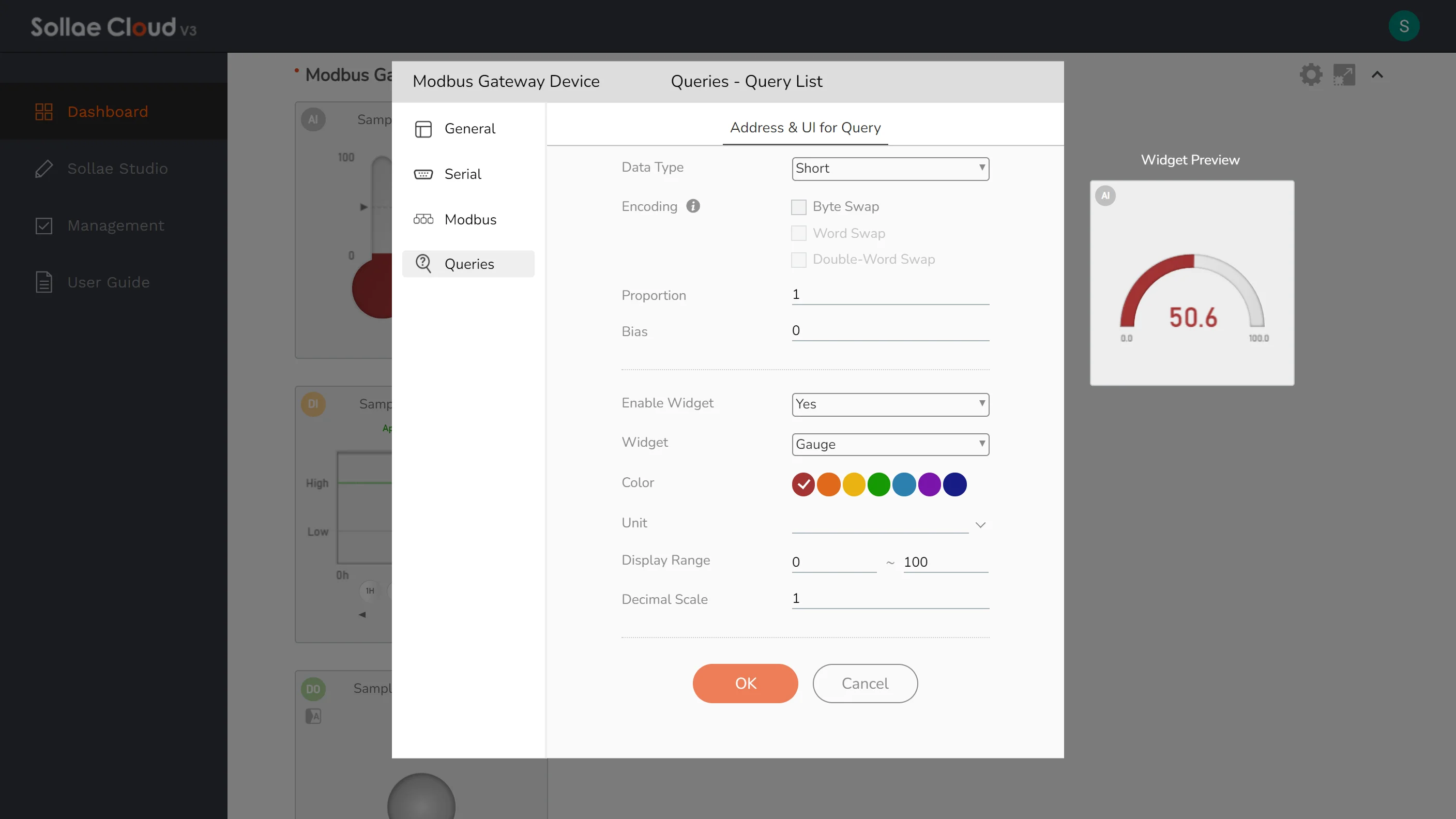
Data Type: Select the data type of the response data. Users can choose between Short (16-bit integer), Unsigned Short (16-bit unsigned integer), Integer (32-bit integer), Unsigned Integer (32-bit unsigned integer), Float (32-bit), or Double (64-bit).
Encoding: Select the swap options for the response data. You can click on the information mark icon to view the sample encoded data.
Proportion: Set the proportion for scaling the response data. The output value will be multiplied by the specified proportion. The default value is 1.
Bias: Set the bias for adjusting the response data. The output value will be added to the bias. The default value is 0.
Widget UI Settings: Set the widget UI for a query. Similar to Setting via Web App - Widget.
Enable Widget: Show/hide visualization of a query.
Widget: Change the visualization style with our provided widgets.
Color: Select the widget color style.
Unit: Set the displayed unit on a query widget.
Display Range: Set the display range for data visualization. The default value is 0 ~ 100.
Decimal Scale: Set the display format of the analog value as how many digits after the decimal point should be displayed. If set to 0, any floating-point value will be rounded to an integer.
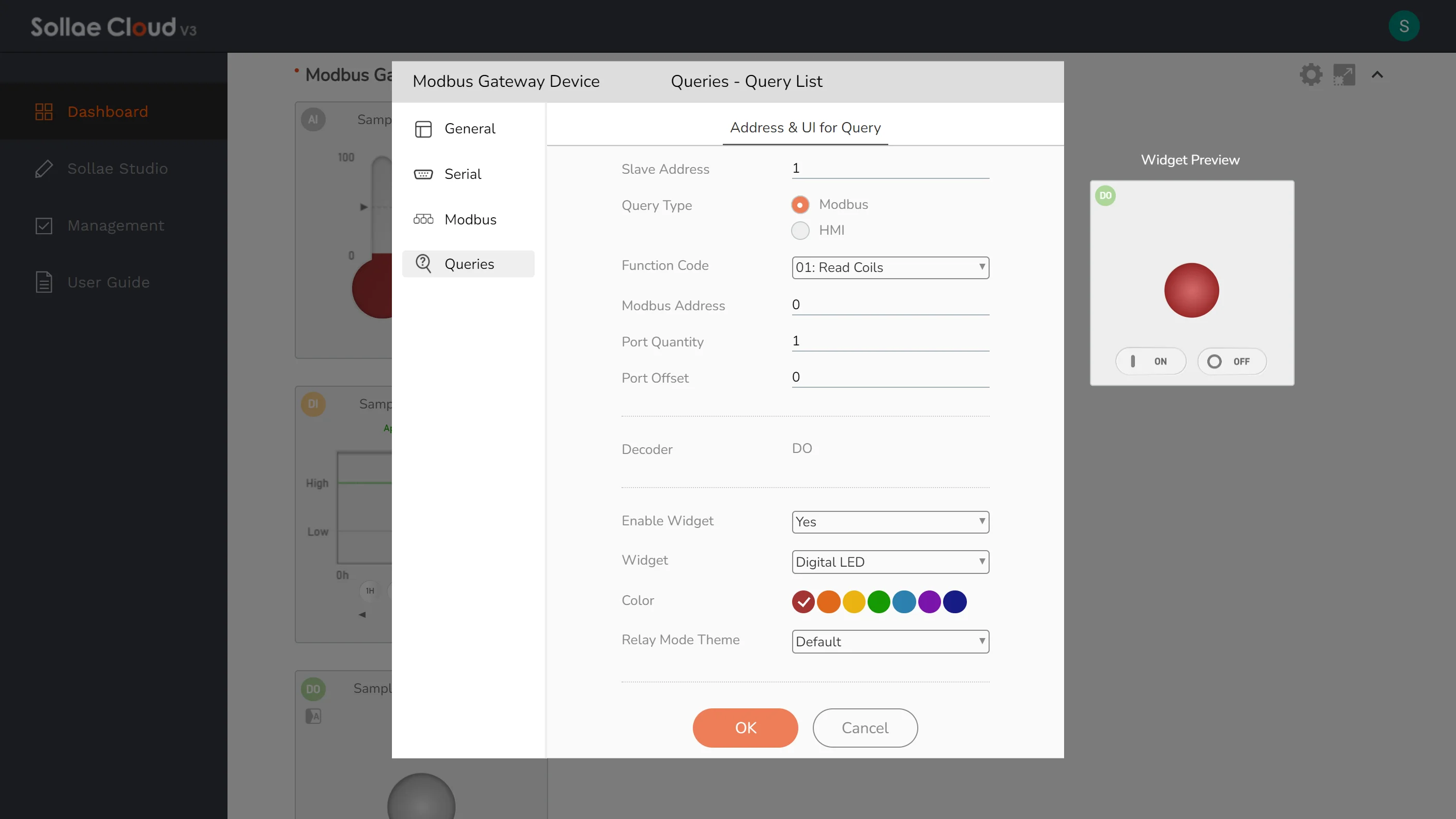
When a query is configured with Read Coils (01), it functions as a digital output port, retrieving the digital state with Read Coils (01). Control is then initiated by sending a request to the corresponding Modbus address using Write Single Coil (05).
For Digital Output control, SMG models support only ON or OFF commands, with no delay. TOOGLE and PULSE commands are not supported. It is recommended to send one control command at a time and wait a few moments for the device response, before sending another command.
The maximum number of queries per device is 8.
In the web app, the Query Type setting lets you choose between Modbus and HMI, which correspond to two address formats: Modbus Addresses (starting at 0) and HMI Addresses (starting at 1 with a function code prefix). Below, we explain how these addresses relate and how to configure Port Quantity and Port Offset.
| Query Type | Modbus | HMI | ||
|---|---|---|---|---|
| Function Code (Read) | Function Code (Write) | Modbus Address | HMI Address | |
| Digital Output | Read Coils (01) | Write Single Coil (05) | xxxxx | 0xxxxx + 1 |
| Digital Input | Read Discrete Inputs (02) | xxxxx | 1xxxxx + 1 | |
| Analog Input | Read Holding Registers (03) | xxxxx | 4xxxxx + 1 | |
| Analog Input | Read Input Registers (04) | xxxxx | 3xxxxx + 1 | |
For example, with Query Type set to HMI and a Modbus Address of 4 for Read Discrete Inputs (02), the HMI Address is 100005. Here, 1 is the prefix for Function Code 02, and 00005 is Modbus Address 4 + 1.
Port Quantity (number of digital I/O ports to read) and Port Offset (which port in that digital I/O ports to use) are used to read digital data from Modbus slaves, such as Digital I/O (e.g., function codes 01, 02). These settings do not apply to analog data (e.g., function codes 03, 04).
For most setups, like reading a single Digital Input or Output, set the address to your desired value (Modbus or HMI based on Query Type), Port Quantity to 1, and Port Offset to 0 to get the data value.
If a slave only responds to specific query frames, you may need to adjust settings. Below are examples for two common cases to read the 4th discrete input:
Case 1: Slave supports direct addressing.
If your slave lets you target a specific input, use these settings to read the 4th input:
For Modbus Query Type: Modbus Address 3, Port Quantity 1, Port Offset 0.
For HMI Query Type: HMI Address 100004, Port Quantity 1, Port Offset 0.
Case 2: Slave requires a block read.
If your slave only responds to a block starting at 0, read multiple inputs and pick the 4th:
For Modbus Query Type: Modbus Address 0, Port Quantity 8, Port Offset 3.
For HMI Query Type: HMI Address 100001, Port Quantity 8, Port Offset 3.
Event for Query is only accessible after a query is saved.
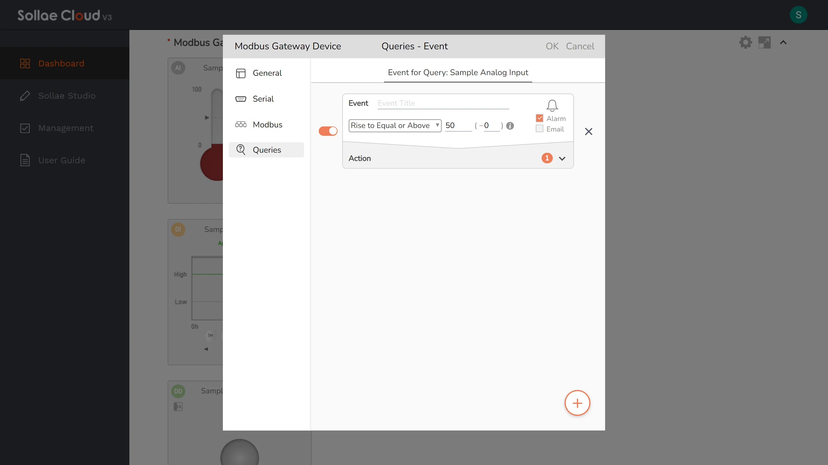
Event feature is only available for the queries saved as Analog Input or Digital Input. Otherwise, if a query is set as Digital Output, Action for Query will be available.
The configuration window aligns with the one featured in Setting via Web App - Event.
Action for Query is only accessible after a query is saved.
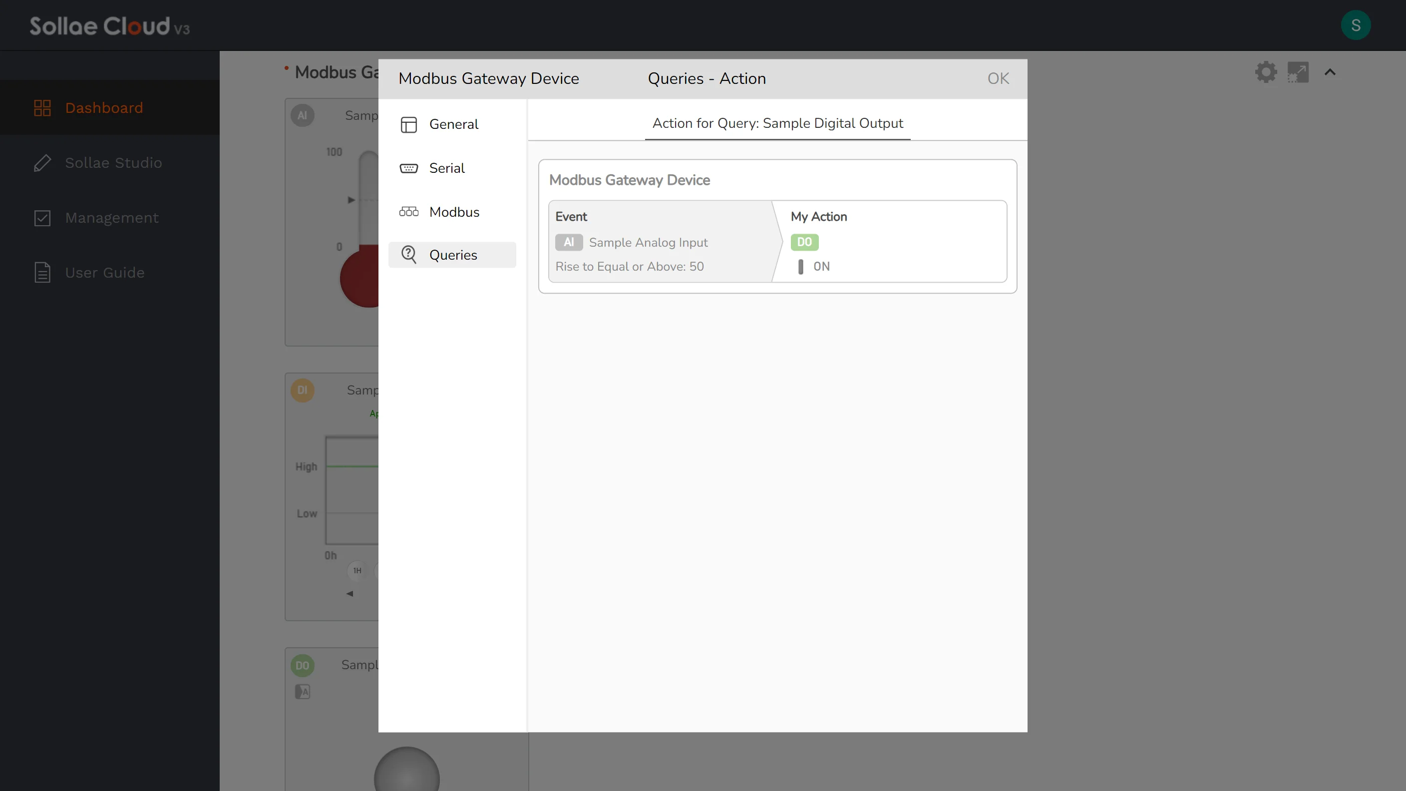
Action feature is only available for the queries saved as Digital Output. Otherwise, if a query is set as Analog Input or Digital Input, Event for Query will be available.
The window aligns with the one featured in Setting via Web App - Action.
Actions targeting digital output on the SMG models support only ON or OFF commands with no delay.
Overview
Collect all the data you need for understanding, evaluating, and controlling your system.
SIG models gather data from sensors and equipment, sending it to the cloud server every minute. For analog input ports and thermometers, the approach is similar. The average value is used to represent the measured value if there are different analog values collected during a specific period. Besides regular updates, if the value changes by more than 3% for analog inputs or by 0.5 degrees Celsius for thermometers, it will be promptly updated with a brief delay. As for digital I/O ports, they are regularly updated, and any changes in the logic state are reported nearly immediately with minimal delay. With Sollae Cloud, you can rely on up-to-date data that is continuously refreshed in real-time, ensuring a high level of time precision.
SMG models employ a data polling mechanism, querying information from Modbus slaves every 5 seconds. In cases of a detected value change, it promptly sends the update to the cloud. Any state change in Modbus slave is expected to be sent to the cloud within 5 seconds. Otherwise, similar to Sollae IoT Gateway devices, it sends the data retrieved from slaves to the cloud every minute. This applies to both Analog and Digital values.
Supported Model
SIG-5431
SIG-5441
SIG-5451
SIG-5561
SIG-5601
SMG-5511
SMG-5521
How to use
Sollae Cloud web UI is ready-to-use for monitoring. You can watch your devices on the dashboard page, or expand the view for a particular device/port. Remember to choose a suitable theme for the dashboard.
For configuration, visit the Widget and the Device categories on the Setting page.
The update rate relies on Sollae devices since Sollae Cloud instantly ships any data received from the devices. Basically, digital I/O ports update with a typical delay of approximately 1 second for changes in logic state, while analog input ports and thermometers have a typical delay of around 2 seconds for updates triggered by changes exceeding predefined thresholds.
Overview
We provide Sollae devices equipped with relay outputs. By integrating the devices into your system, you can remotely control things as you want via Sollae Cloud.
Supported Model
SIG-5451
SIG-5601
SMG-5511
SMG-5521
How to use
For configuration on SIG models, visit Command Buttons in the Widget category on the Setting page. Set up the commands you want to use for controlling relay outputs.
For SMG models, you have to create a query and set it as digital output. Modbus query only supports two fixed control commands, ON and OFF, with no delay option.
To send a control command, just press the button shown in the port widget UI. The device will execute the requested command on its digital output port.
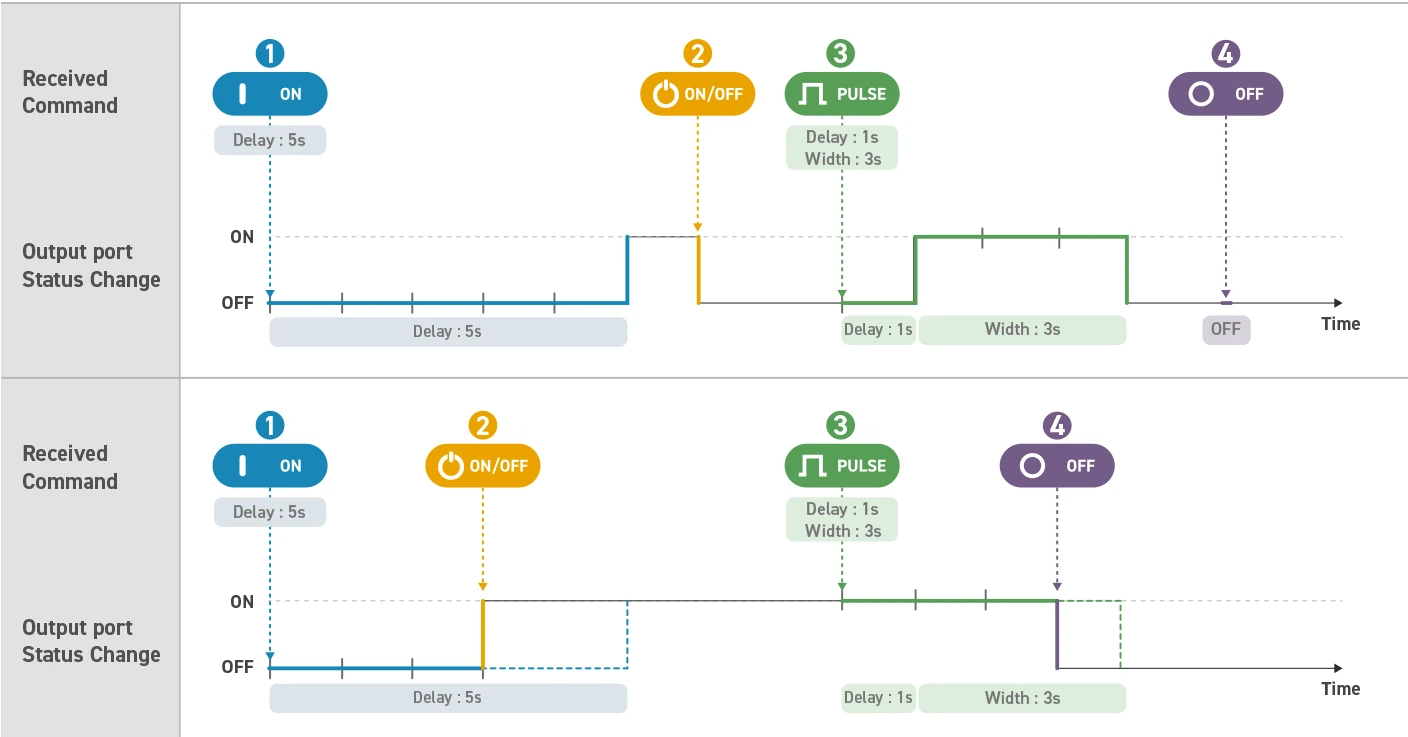
Upon a device receives a control command, the command will be processed immediately. The execution time of each command includes the delay and the output generation time. Thus, if you send lots of commands within a small period that causes overlap between their execution time, then the later-sent one will override the previous ones' execution.
Overview
The fundamental use of digital inputs is to acquire input signals. Apparently, it is important to know the logic state. Besides, it can be useful to watch the number of digital edges, in other words, how many times the low-to-high (rising edge) or high-to-low (falling edge) transition of the input signal happens. This feature gives you an advanced tool to capably monitor your system.

Supported Model
SIG-5441
SIG-5601
How to use
For configuration, visit the Device category on the Setting page.
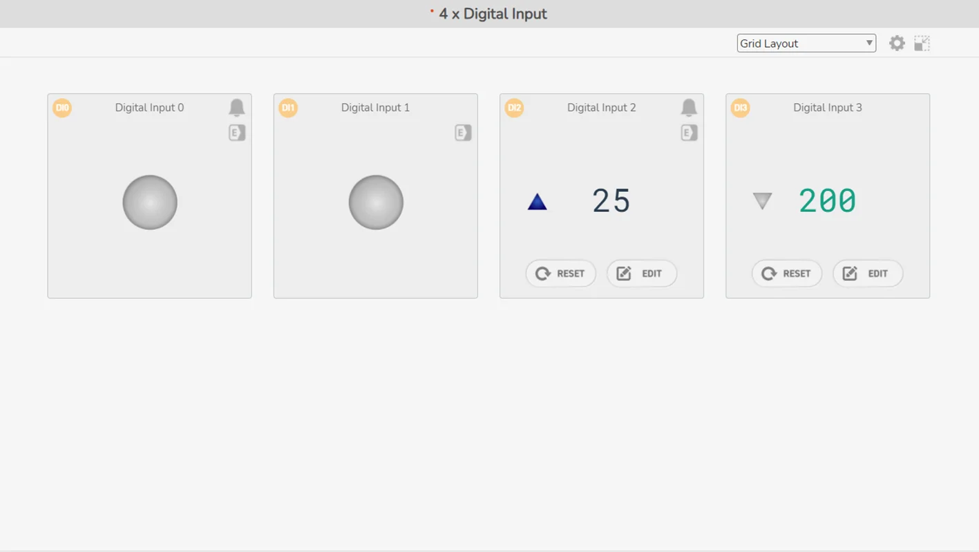
Users can click the RESET button to reset the counter to the Default Counter Value.

The counter value can also be set by users. Just click the EDIT button on a digital input widget to proceed.
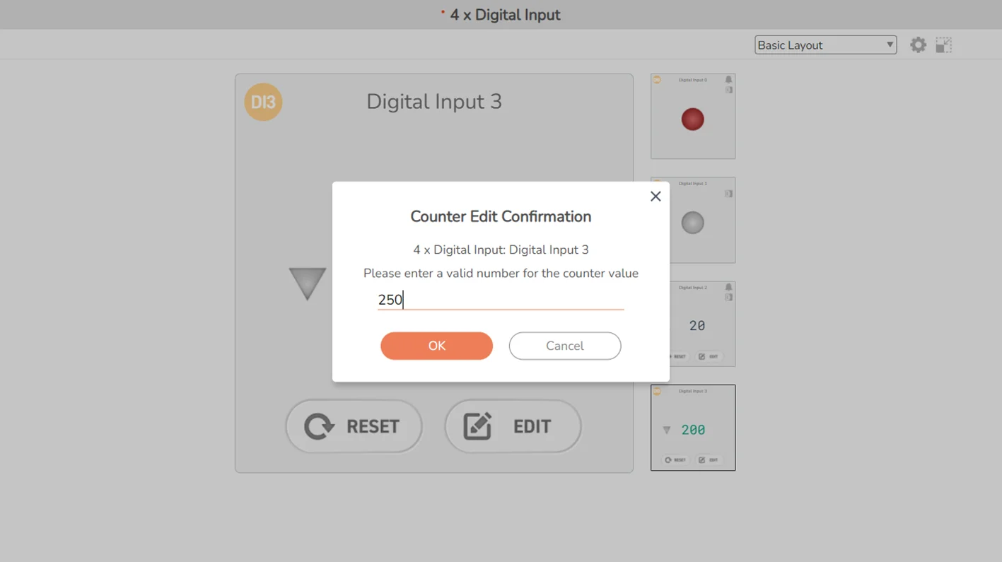
Sollae devices support 32-bit integer counter values, so please input a valid number.
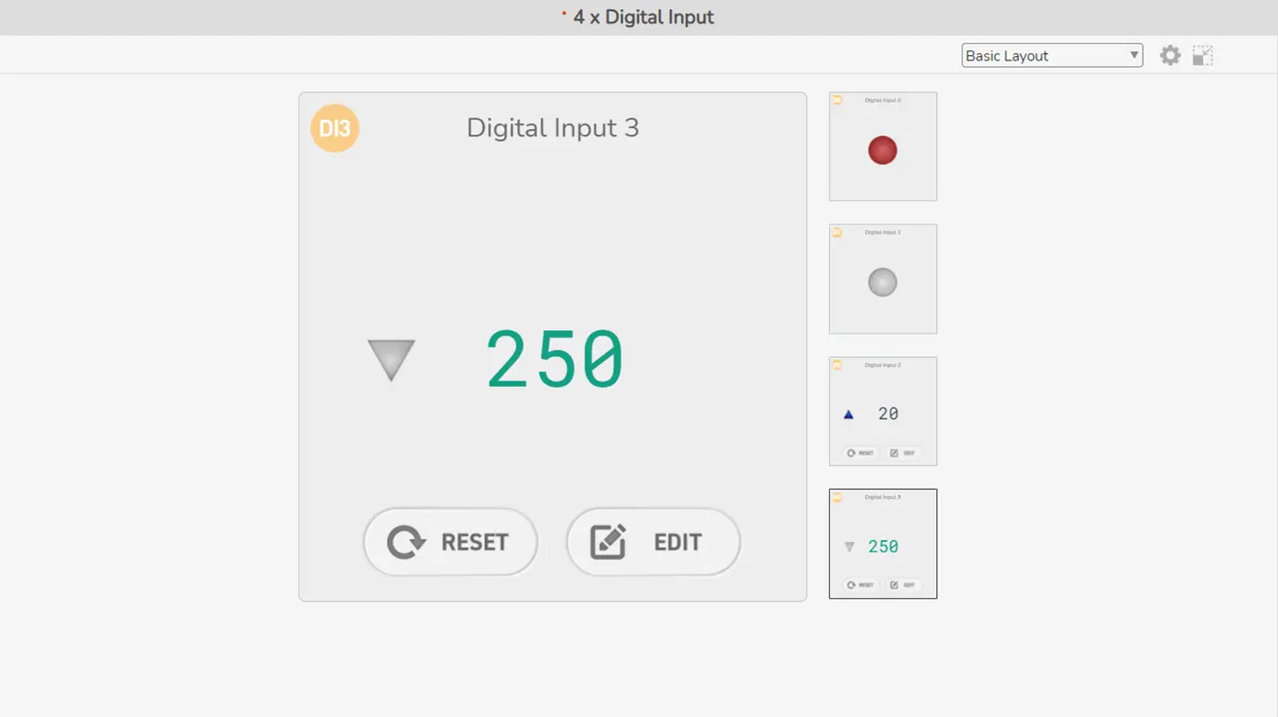
Tip: Set the widget of the digital input port as Counter to better keep track of counter value. The Counter widget will display the current counter value, with a state indicator aside to demonstrate the port state.
Read more: Setting Page - Device
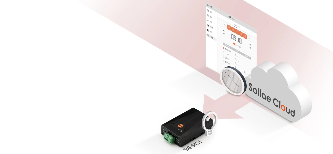
Overview
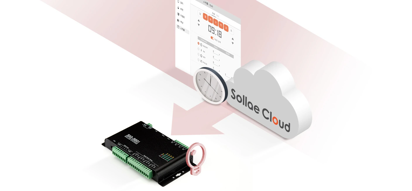
If you wish to turn your manually-control system to a scheduled-automation one, then Schedule is for you. Set up weekly or one-time schedules to make everything work automatically. You can specify the schedule and the output control you wish, which includes setting the output to on/off or generating a pulse.
Supported Model
SIG-5451
SIG-5601
How to use
For configuration, visit the Schedule category on the Setting page. Remember to set the correct timezone, otherwise the scheduling function may not work as you expect.
Once schedules are set for a port, a shortcut to access Schedule configuration will be displayed on the port widget.
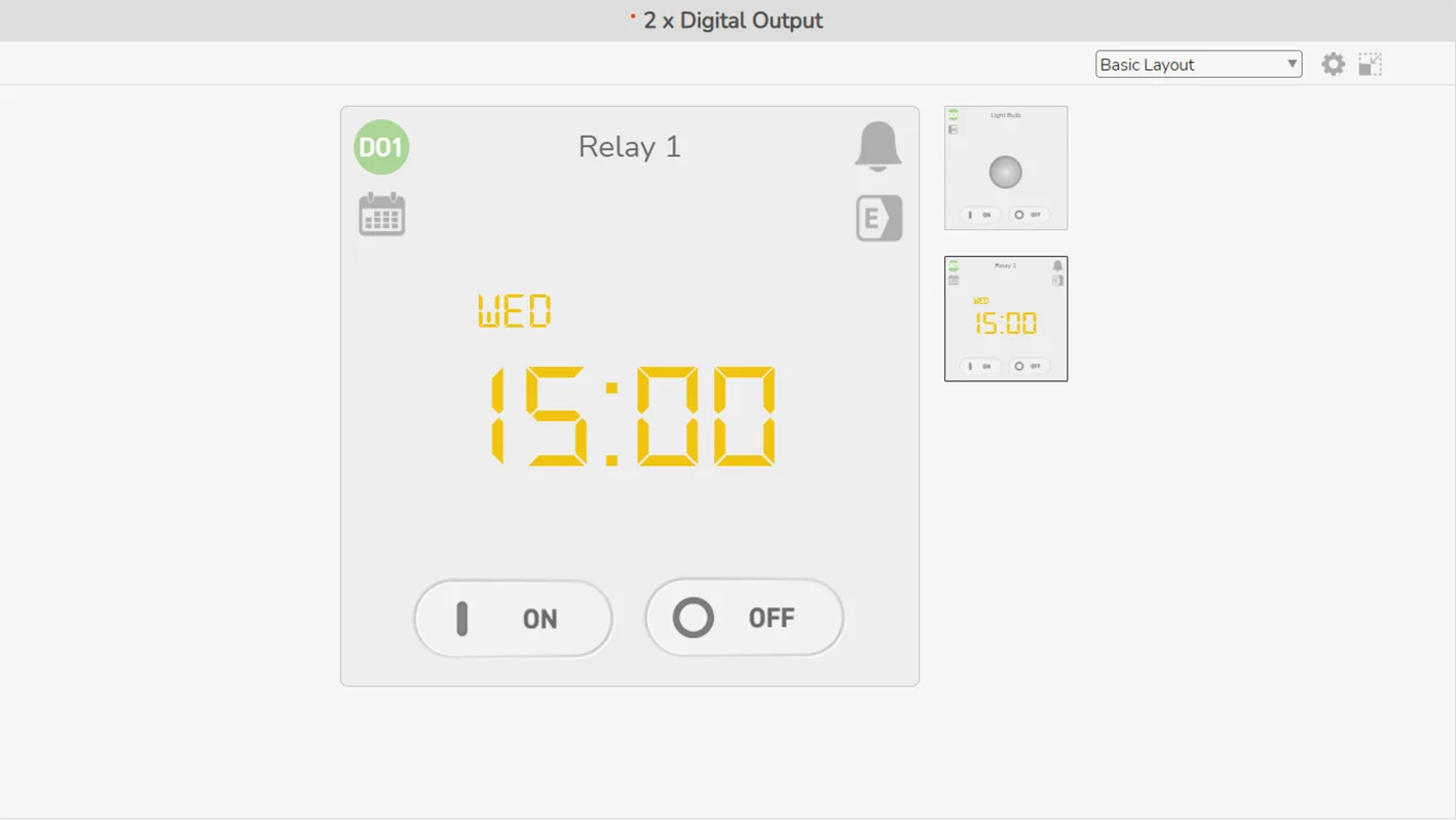
Tip: Set the widget of the digital output port as Scheduler to keep track of the schedule. The Scheduler widget will show the next schedule set to be executed on the port. Note that the Scheduler gets the date/time information from the host device (your PC/mobile), so please make sure the date/time of the host device is set correctly.
Please be aware that our Schedule function is subject to limitations imposed by AWS. The time precision provided is limited to around several seconds.
Please be aware that our Schedule function is subject to limitations imposed by AWS. The time precision provided is limited to around several seconds.
Read more: Setting Page - Schedule, Multi-controlling
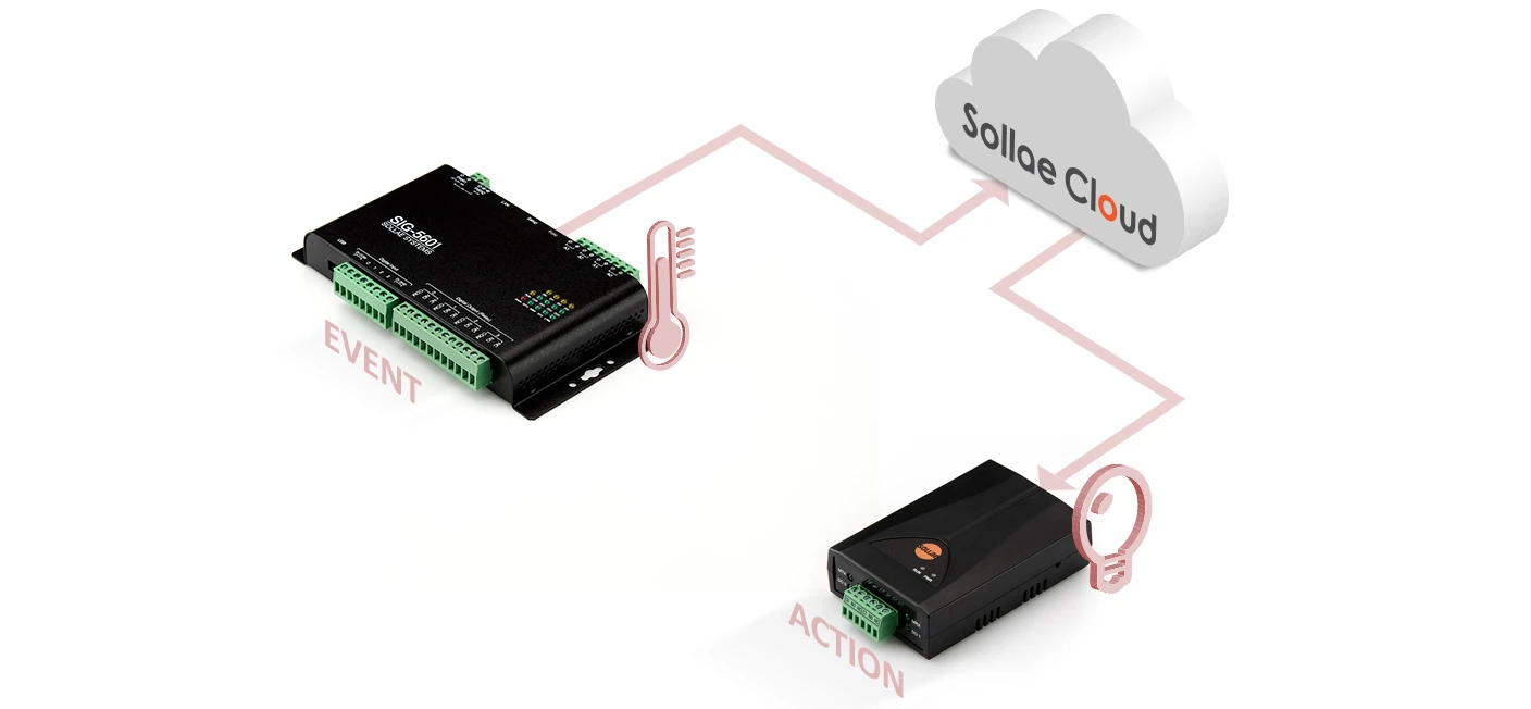
Overview
This feature assists you to be reactive to your system. It covers any updates of the analog value in analog input ports, the logic state changes in digital I/O ports, and the counter for signal changes in digital input ports. Just specify the device's operating conditions as events, then when an event occurs you can get alarmed, email notification, and/or automatically call the response actions. Currently, the supported response actions include controlling output ports.
Supported Model
SIG-5431
SIG-5441
SIG-5451
SIG-5561
SIG-5601
SMG-5511
SMG-5521
How to use
For configuration, visit the Event category on the Setting page.
Once events are set for a port, a shortcut to access Event configuration will be displayed on the port widget. If you set the dashboard theme as Normal View, the analog input widgets may provide the indicators to mark the Set Value of the enabled events.
It is not recommended to define the events that are likely to occur too frequently. Although the purpose of the feature is to keep you proactive with your system, having too many event occurrences within a short time may be difficult to monitor, and that also makes your system seem volatile as well.
Read more: Setting Page - Event, Setting Page - Event for Query
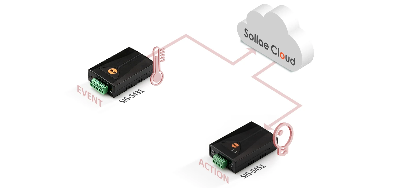
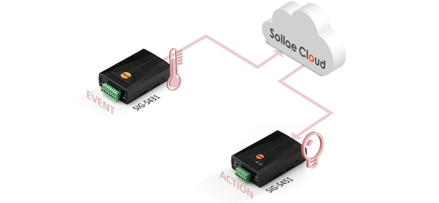
Overview
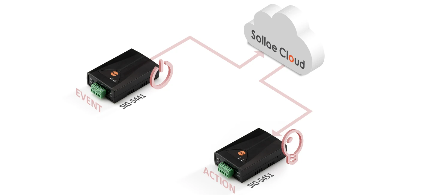
If you are familiar with Sollae I/O products, you may know about Internet Switch, a function that allows transferring digital I/O states via the Internet. With Internet Switch, any state changes in digital inputs ports may be directed to control digital output ports somewhere else. You may achieve more than that with the Action feature on Sollae Cloud, as you are now able to control digital output ports in response to not only digital input state changes but any user-defined events within your system.
A user-defined event can be made from any device, but the target for the action should be a model with digital output ports. Supported actions include setting the output to on/off or generating a pulse.
Supported Model
SIG-5451
SIG-5601
SMG-5511
SMG-5521
How to use
The first thing to do is to determine under which event condition and from which device/port you wish to trigger the action, and which device/port should be the target that executes the action. For configuration, visit the Event category on the Setting page of the trigger device.
Once actions are targeted for an output port, a shortcut to view the available actions will be displayed on the port widget.
On the Action page, you can see the list of events that triggers action on an output port, grouped by the trigger device.
On the setting page, the Action category is read-only. However, you can click on an item to view/edit the trigger event.
An action execution may cause an event to occur. On the other hand, an event occurrence may lead to an action to be triggered. Please be careful to avoid setting a closed loop of the events and actions, which may trigger an infinite chain of actions inside your system.
Overview
The alarm function is designed to inform users of the occurrence of a user-defined event.
As a client-side feature run by the web app, this is helpful in case users keep an open window for real-time monitoring. Users can be notified via UI visualization and sound when an event occurs.
Supported Model
SIG-5431
SIG-5441
SIG-5451
SIG-5561
SIG-5601
SMG-5511
SMG-5521
How to use
For configuration, remember to check the alarm option if you want to get alarmed for a particular user-defined event.
Once alarm-set events are enabled for a port or a Modbus query, an alarm icon will be displayed on the widget.
When an alarm-set event occurs, the alarm icon will turn red. You can quickly dismiss alarm effects by clicking on the alarm icon. A notification panel will show up at the bottom of the browsing window to display the list of your devices that have alarms occurring. The panel allows you to view a device in an expanded window, dismiss the existing alarm effects on each or all of those devices.
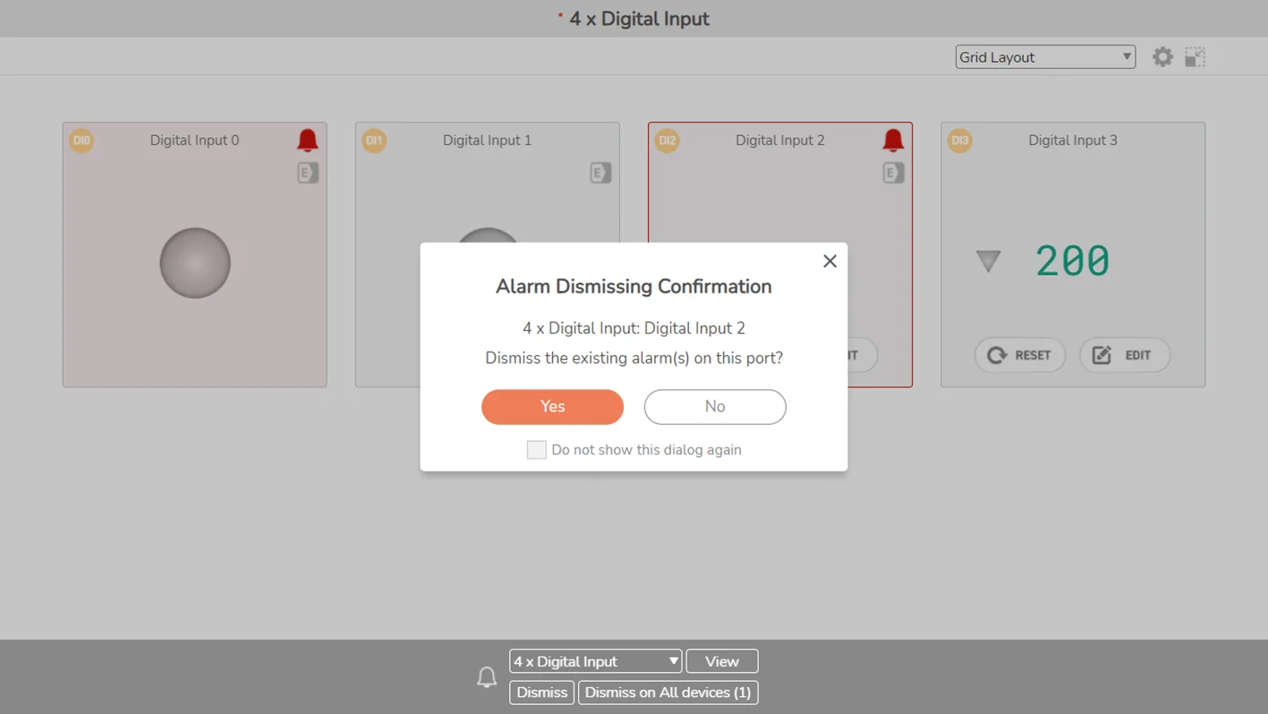
You can also stop the effects manually by opening the Event configuration window, then click on the now-blinking alarm indicator to proceed. This could be helpful if there are many alarm-set events on a port and you wish to see exactly which ones are occurring.
If an event is naturally ceased, its alarm effects will be stopped automatically. The effects will arise if the event occurs again. Uncheck the alarm option in the configuration if you do not want alarm effects for an event.
The alarm effects are not usable if your web app is disconnected from our MQTT server. It may also be unavailable for any device that is not being connected to our server.
On desktop browsers, you can turn on Alarm Sound for sound effects.
Read more: Setting Page - Event, Setting Page - Event for Query
Overview
The email notification can be used to inform users of the occurrence of a user-defined event.
Users can be notified via email when an event occurs.
Supported Model
SIG-5431
SIG-5441
SIG-5451
SIG-5561
SIG-5601
SMG-5511
SMG-5521
How to use
For configuration, ensure to select the email option if you wish to receive email notifications for a particular user-defined event.
Once email notification events are activated for a port or a Modbus query, an email icon will be displayed on the widget.
When an event takes place on a port or a Modbus query, users will receive notifications via the email account associated with the devices registered to Sollae Cloud. Please check your Spam folder if you cannot find our notification email in your Inbox.
Read more: Setting Page - Event, Setting Page - Event for Query
Overview
Design custom User Interface for the device monitoring/controlling applications with Sollae Studio.
Supported Model
SIG-5431
SIG-5441
SIG-5451
SIG-5561
SIG-5601
SMG-5511
SMG-5521
How to use
Read more: Introduction to Sollae Studio
Overview
The Device Data Logging function on Sollae Cloud records device historical data, and all associated activities, including user-defined events, event-based actions, schedules, and web-based controls. This feature provides a transparent overview of device operations, facilitating analysis, troubleshooting, and historical reference.
Supported Model
SIG-5431
SIG-5441
SIG-5451
SIG-5561
SIG-5601
SMG-5511
SMG-5521
How to use
The device data is recorded and accessible for users only when the Device Logging Permission is granted. Enable it in User Preference.
If the permission is already enabled, follow these steps: navigate to Device List, select your device, and click the Download button in the Device Data Logging section.
Before downloading, you can select the encoding type for the log file:
UTF-8 (Default): Standard UTF-8 encoding
UTF-8-BOM: UTF-8 with Byte Order Mark
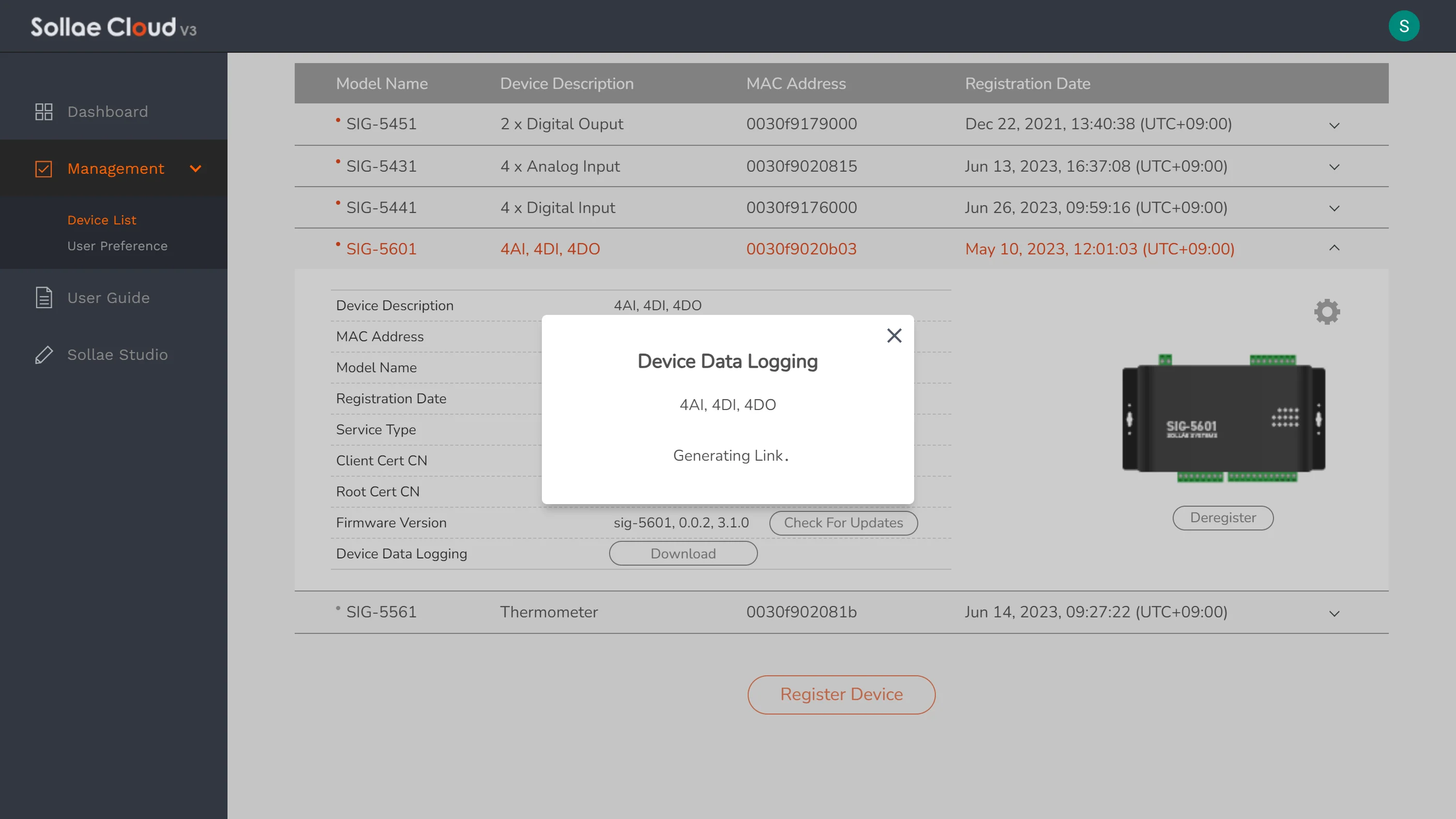
Once generated, you can access the device log data folder by using the provided download link.
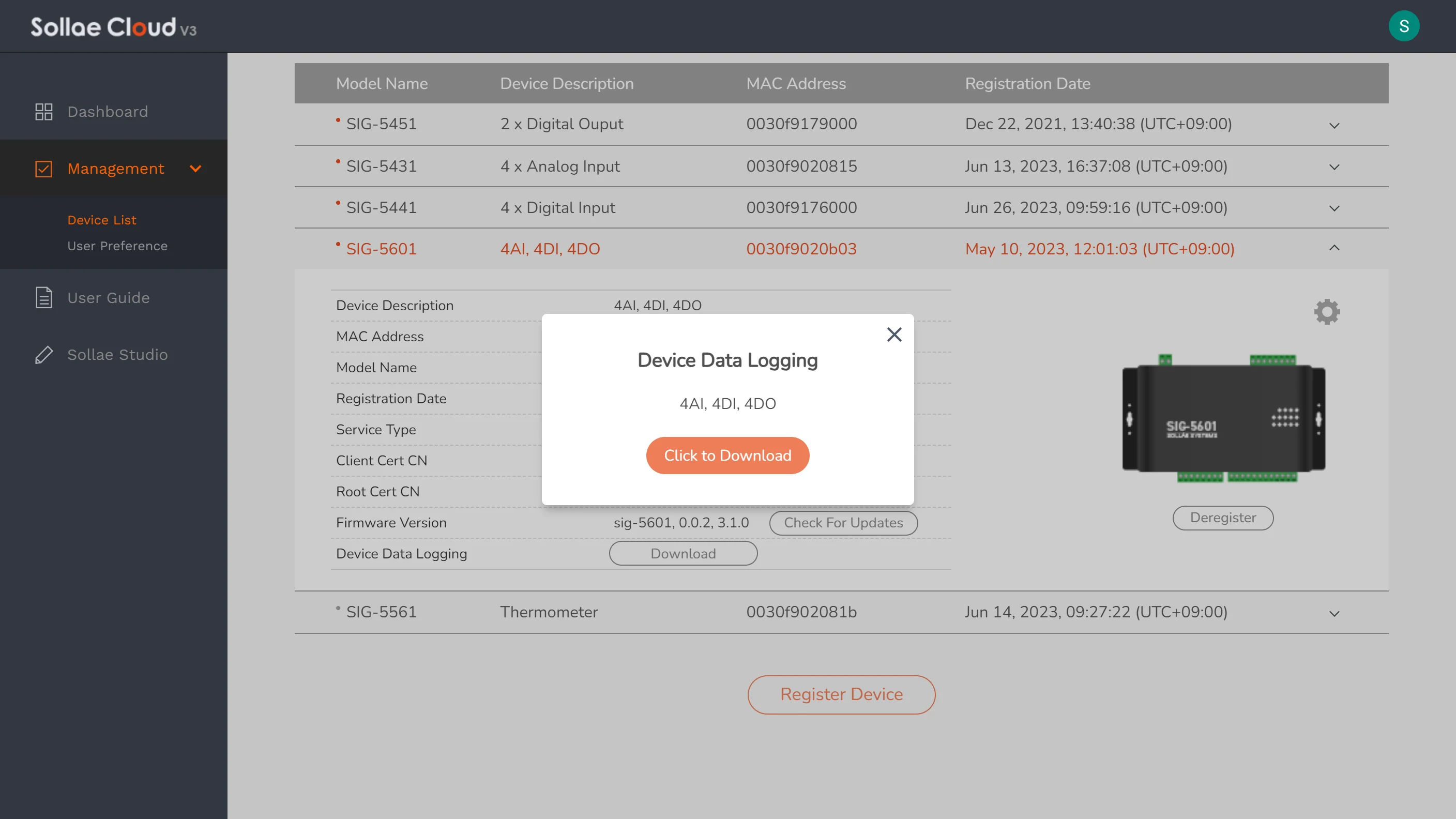
The device data is stored in CSV format, with separate files for each day's log entries. Currently, Sollae Cloud retains device log data for a maximum duration of 30 days. Logging data employs the timezone set in User Preference.
If a user decides to deregister a device, the device recorded data will be permanently deleted from Sollae Cloud.
Overview
Users can check and update the latest firmware version for your Sollae Gateway for Cloud via spFinder, or Sollae Cloud web app. It is recommended to update your device's firmware to the latest version to improve performance and fix bugs.
Supported Model
SIG-5431
SIG-5441
SIG-5451
SIG-5561
SIG-5601
SMG-5511
SMG-5521
How to use
Visit Management Page - Device List. Open the management view of a device your wish to check and then click Check for Update.
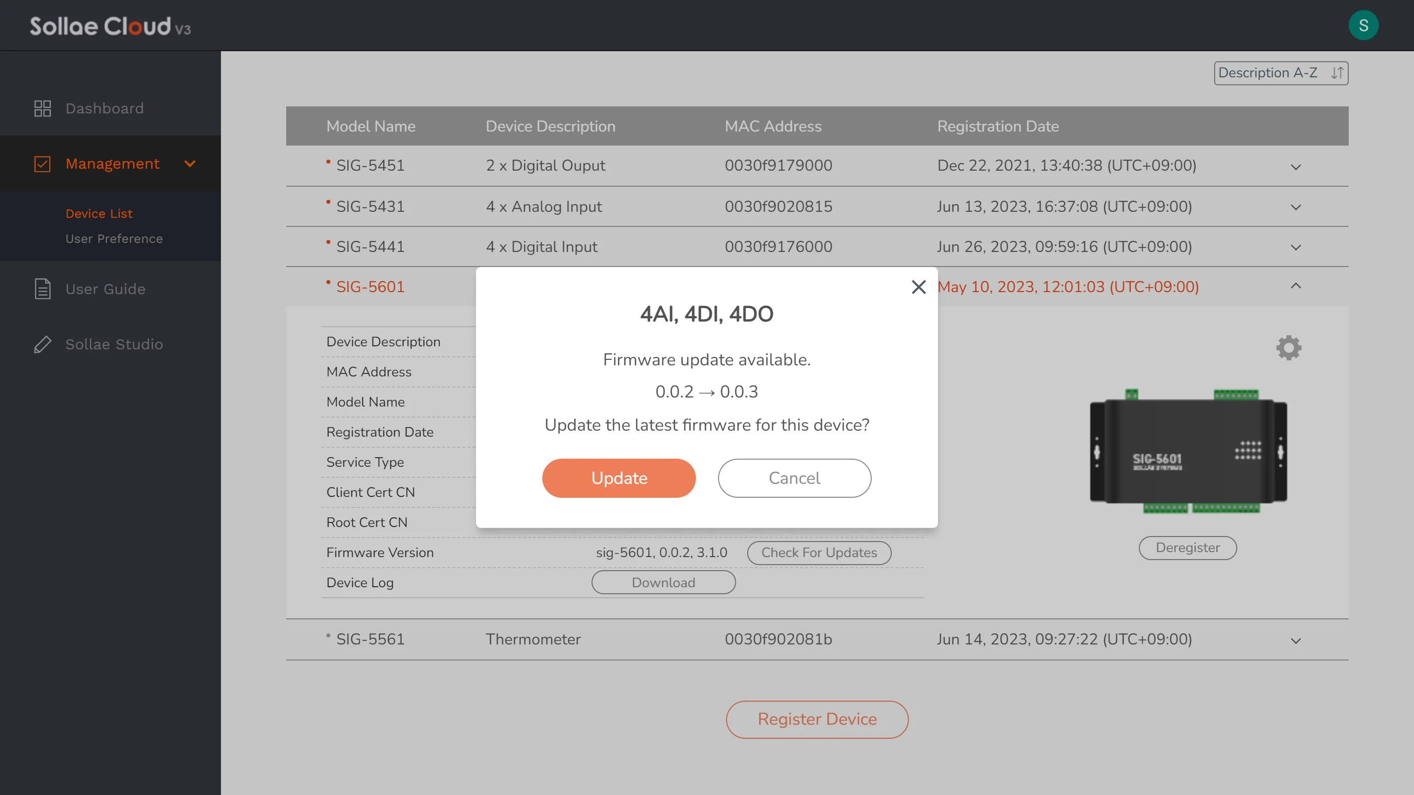
The firmware update process for your Sollae Gateway through Sollae Cloud may occasionally fail due to the memory limitations inherent in embedded devices. However, rest assured that your device will continue to function normally with the current firmware version, and you can attempt the update again at any time.
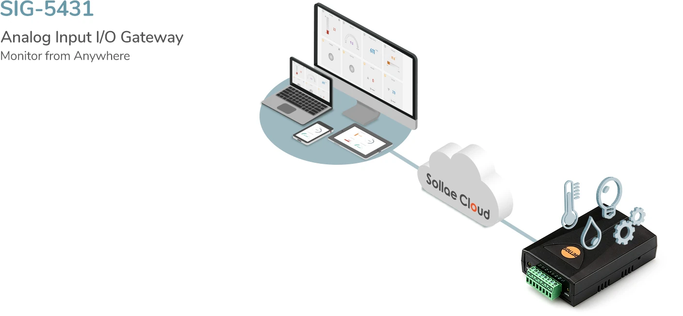
Overview
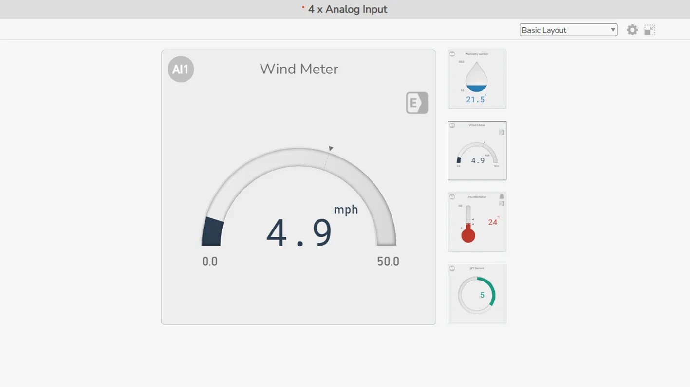
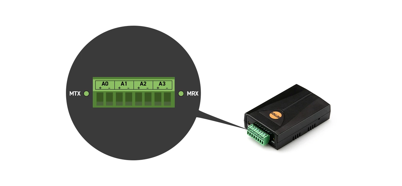
A wired LAN industrial I/O gateway equipped with 4 analog input ports.
Users can remotely monitor the analog sensors connected to this Sollae device. The analog input ports are interfaced with a 3.5mm pitch 8-pole terminal block. The input mode can be selected between voltage (0 ~ 5V), or current (4 ~ 20mA / 0 ~ 20mA).
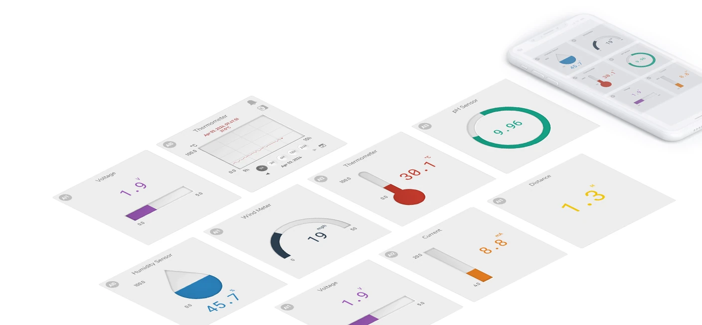
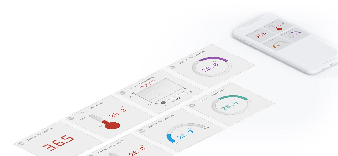
Various widgets provided
There are eight widgets available for analog input, and you can choose the widget you want for your application.
Analog Input Widgets
Text
Gauge
Thermometer
Droplet
Horizontal Progress Bar
Vertical Progress Bar
Circular Progress Bar
Chart (Offering a daily log of a port's state history for up to the last 30 days. Device Data Logging is required for viewing the historical data. The timezone displayed in the chart is aligned with the Device Data Logging feature.)
Event
Users can define events and get alarmed when the actual analog value satisfies the event condition. Alarm effects include a red-blinking visualization on the widget and an alarm sound that is played in the web browser.
The alarm sound is optional and can be enabled each time you start a browsing session.
Besides, you can configure event-based actions targeting the Sollae digital output device (SIG-5451/5601), so the output relay can be controlled based on the analog input state.
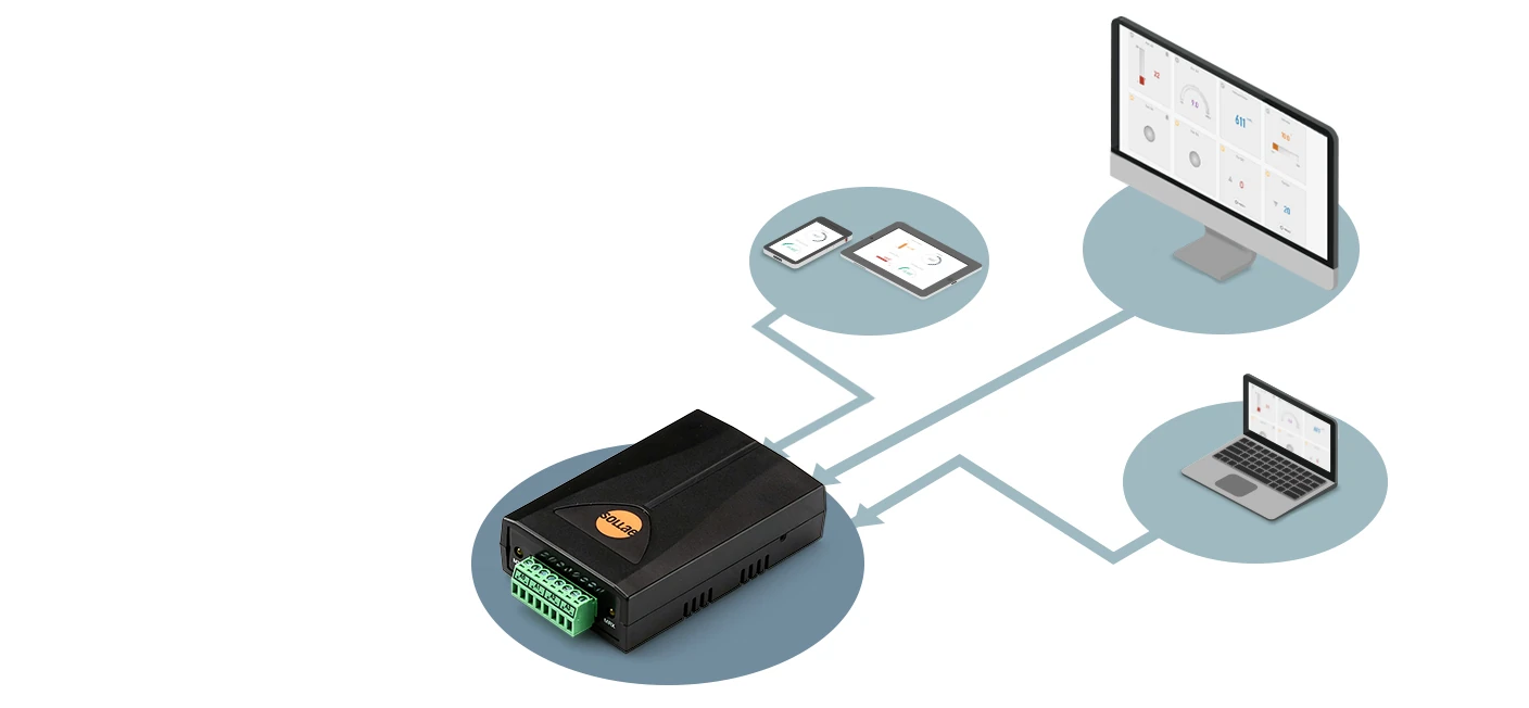
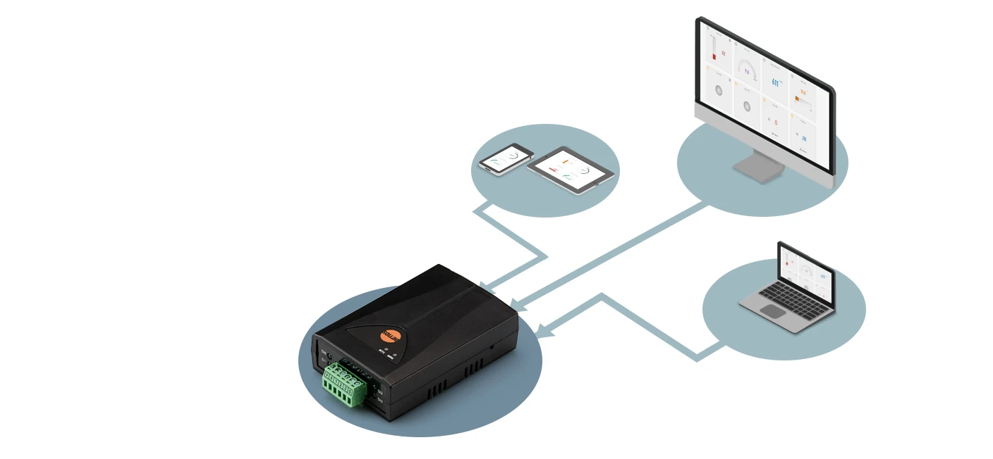
Multi-monitoring
You can view the analog value anytime, anywhere, from multiple locations at the same time, either on a PC or mobile.
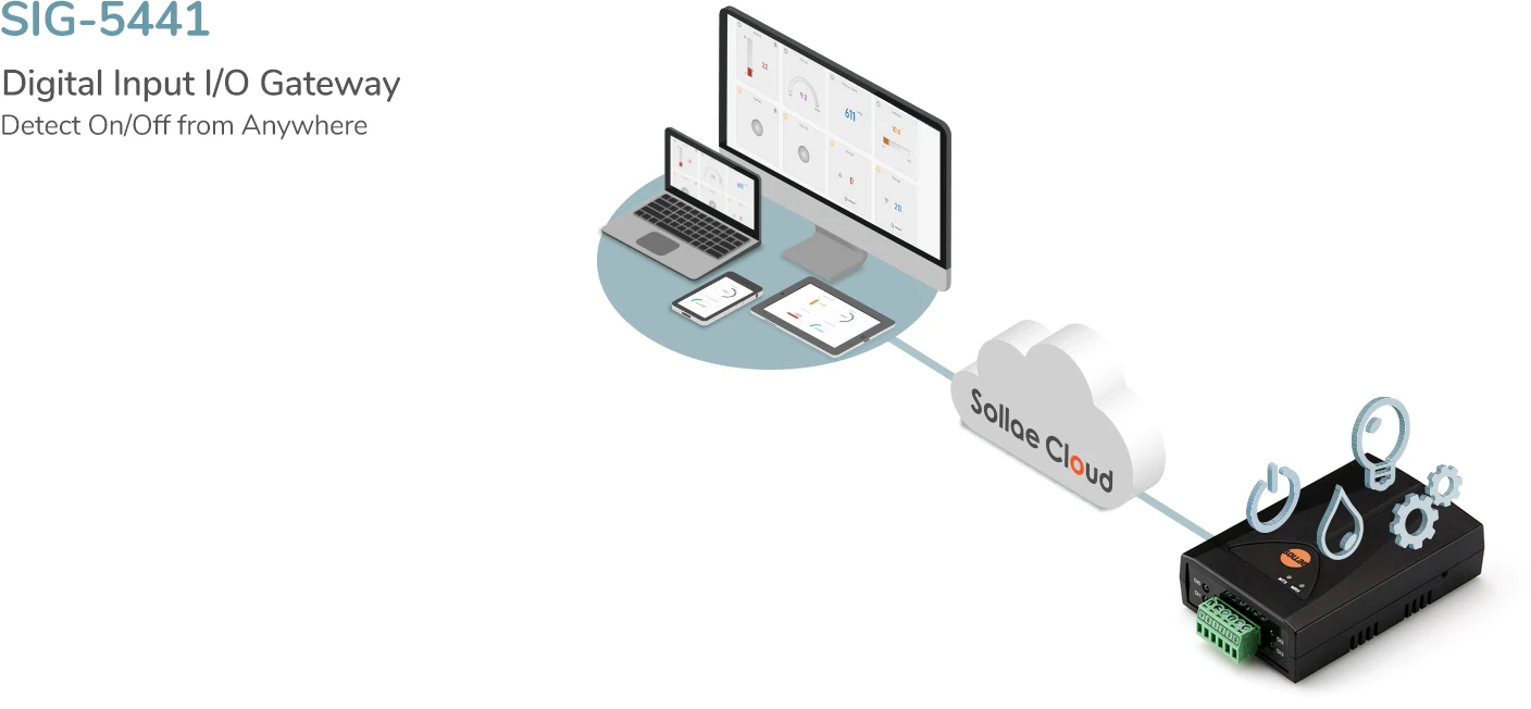
Overview
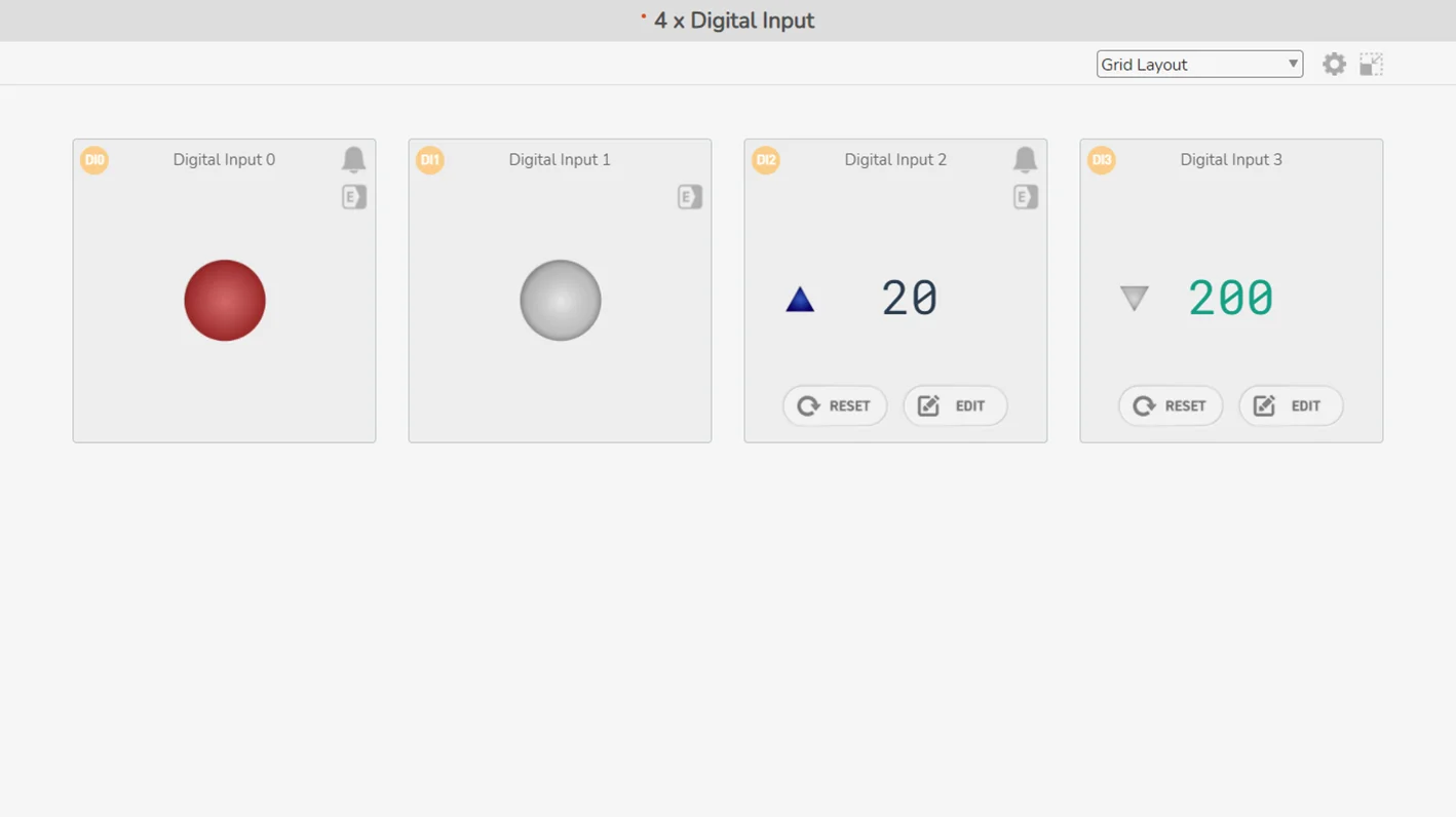
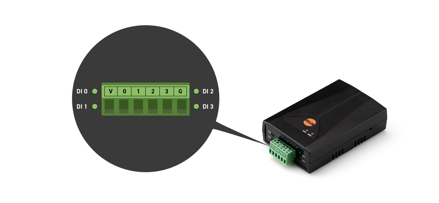
A wired LAN industrial I/O gateway equipped with 4 digital input ports.
Users can remotely monitor the digital output signals of sensors/equipment connected to this Sollae device. The digital input ports are interfaced with a 3.5mm pitch 6-pole terminal block, and Dry/Wet Contact and NPN/PNP input are supported.
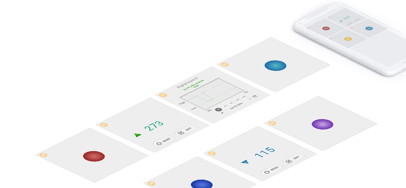
Widgets provided
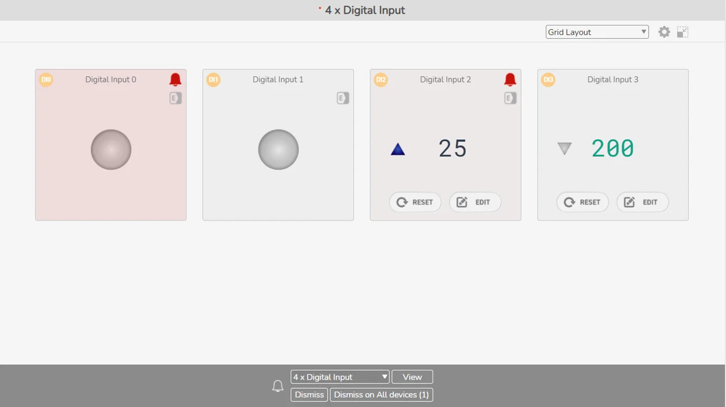
There are three widgets available for digital input.
Digital Input Widgets
Digital LED: Display the ON and OFF state via a round LED. Gray indicates OFF and colored indicates ON state.
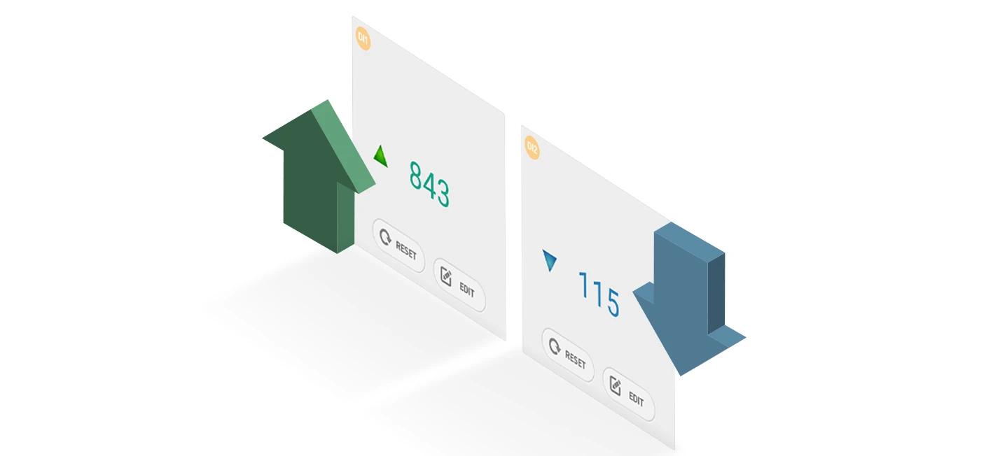
Counter: Include a triangle LED that indicates the ON/OFF state, and the counting value displayed as a number.
Chart: Explore the state history of a port through our chart, offering a daily log for up to the last 30 days. To access this historical data, ensure Device Data Logging is enabled. The timezone displayed in the chart is aligned with the Device Data Logging feature.
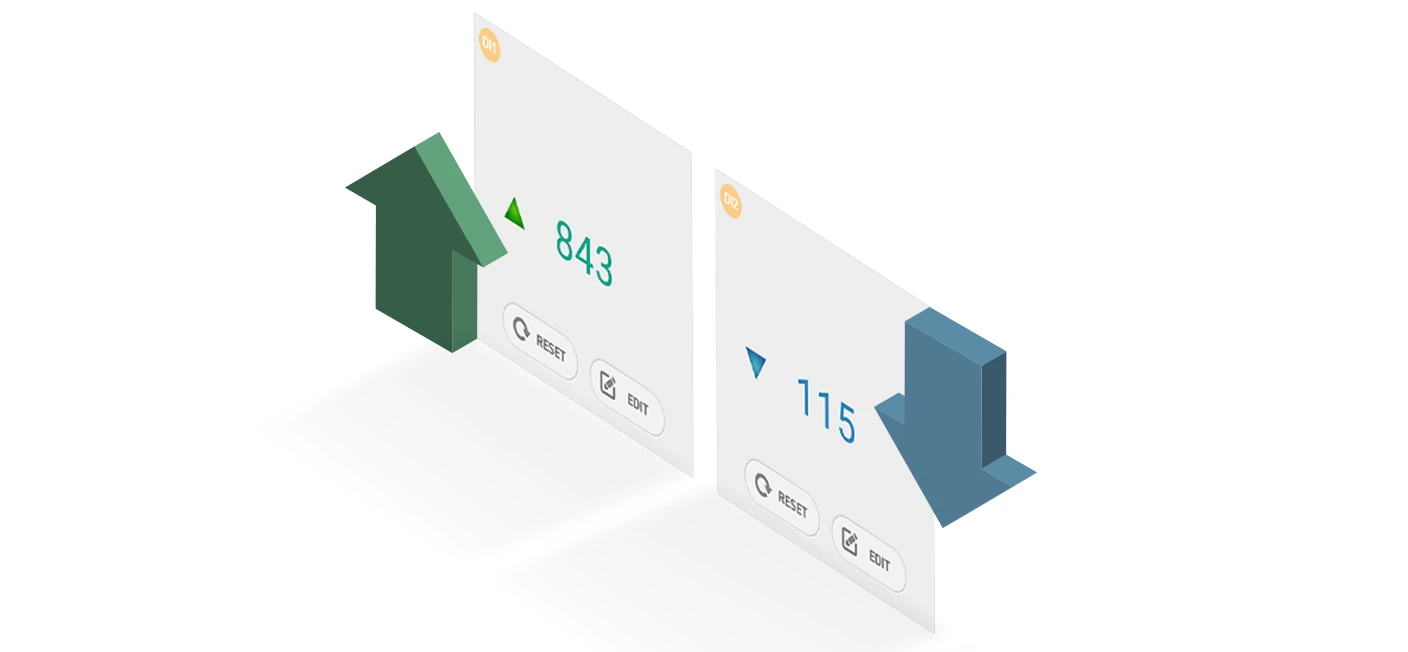
Counter
It is possible to count the number of falling and rising edges of the input signal.
You can set the counter type, counter direction, and default counter value via web app or spFinder. Those are device-stored, which will make the device disconnected from the cloud for a while when you update those configurations, and then the counter will be reset to the default value.
Event
Users can set the event value and get alarmed if the input value or count value meets the event condition. Alarm effects include a red-blinking visualization on the widget and an alarm sound that is played in the web browser.
The alarm sound is optional and can be enabled each time you start a browsing session.
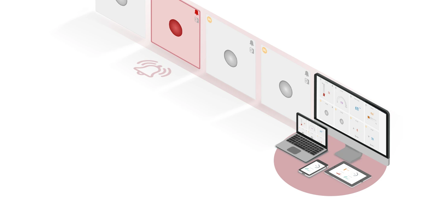
In addition, you can configure event-based actions targeting the Sollae digital output device (SIG-5451), so the output relay can be controlled based on the digital input state.
Multi-monitoring
You can view digital input's logic and counter state anytime, anywhere, from multiple locations at the same time, either on PC or mobile.
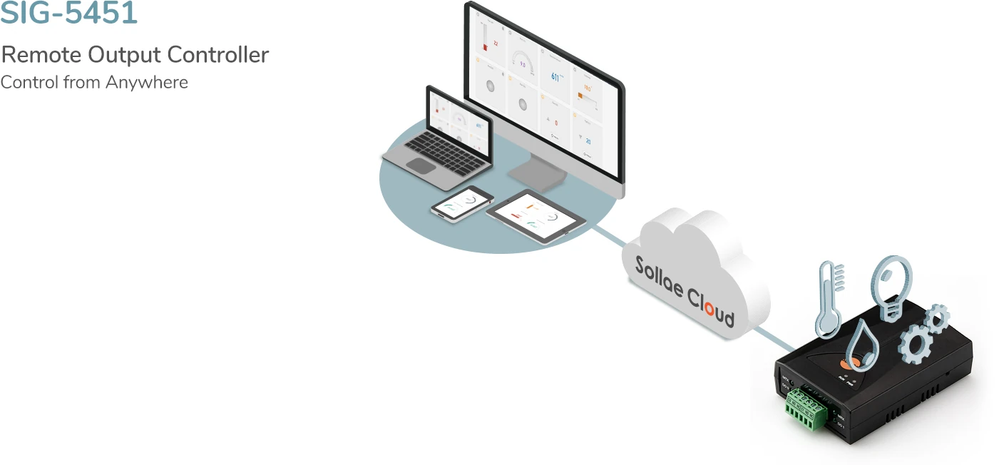
Overview
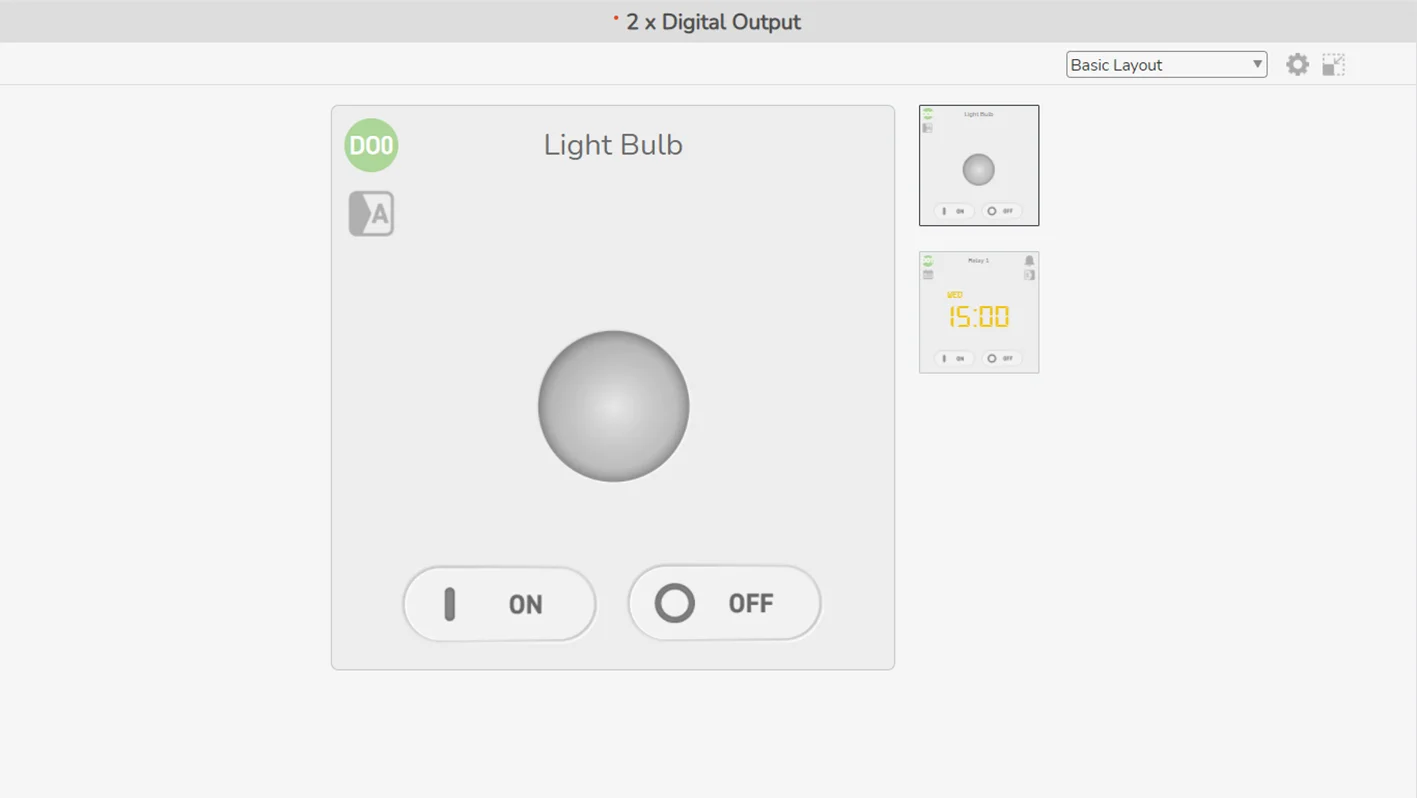
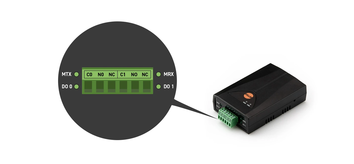
A wired LAN industrial I/O gateway equipped with 2 digital output (relay) ports.
Users can control its relays from anywhere. The digital output ports are interfaced with a 3.5mm pitch 6-pole terminal block. Users can choose between Normal Open and Normal Close mode depending on their application.
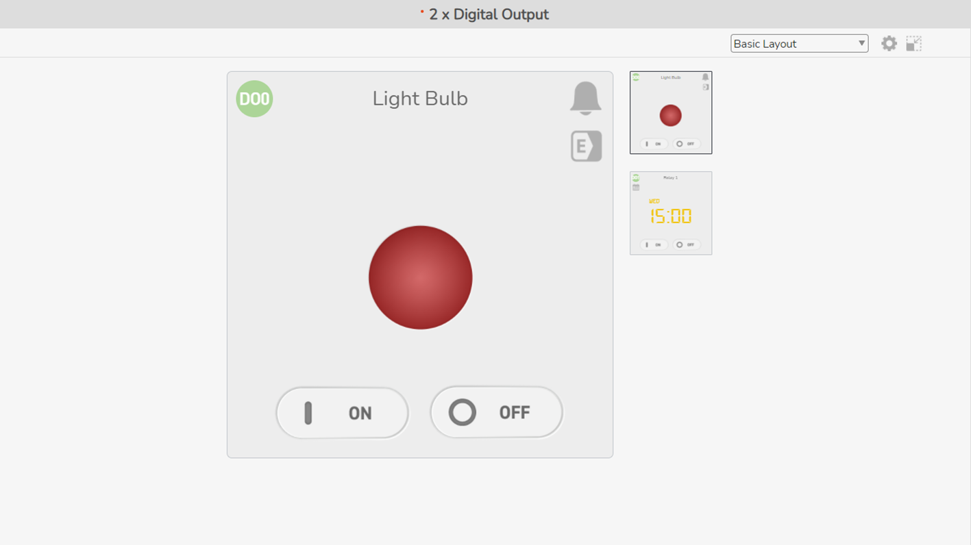
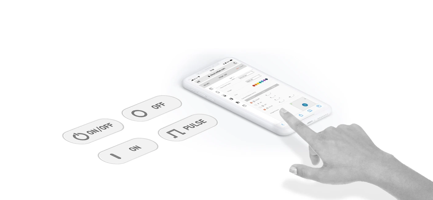
Output Control Commands
The output ports are controlled remotely via Sollae Cloud. The digital output device will execute the control command after receiving it from Sollae Cloud. There are four commands available. Users can set the delay time for a command, and in case of PULSE, the Width can be set. The maximum Delay/Width operation time can be set is up to 30 minutes (1800 seconds).
Digital Output Commands
ON/OFF: Toggle the state of the output port between ON and OFF.
ON: Turn on the output port.
OFF: Turn off the output port.
PULSE: Keep the output port state as HIGH for the Width time and then turn to LOW.
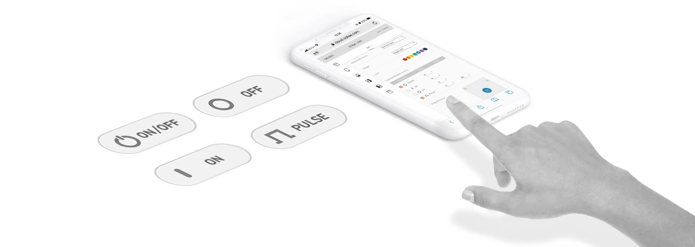
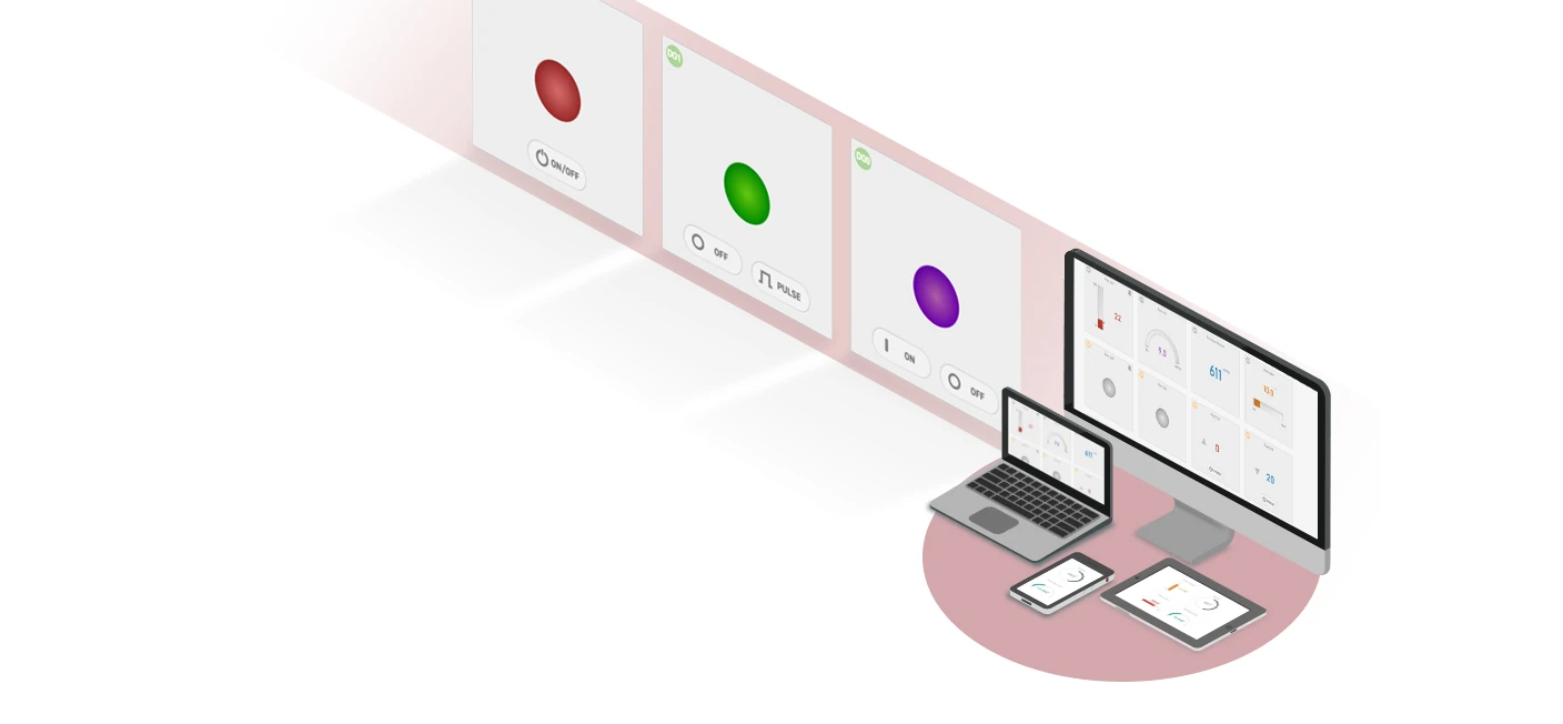
Output Control Methods
An output port can be controlled by three methods: via web, schedule or event-based actions from Sollae devices.
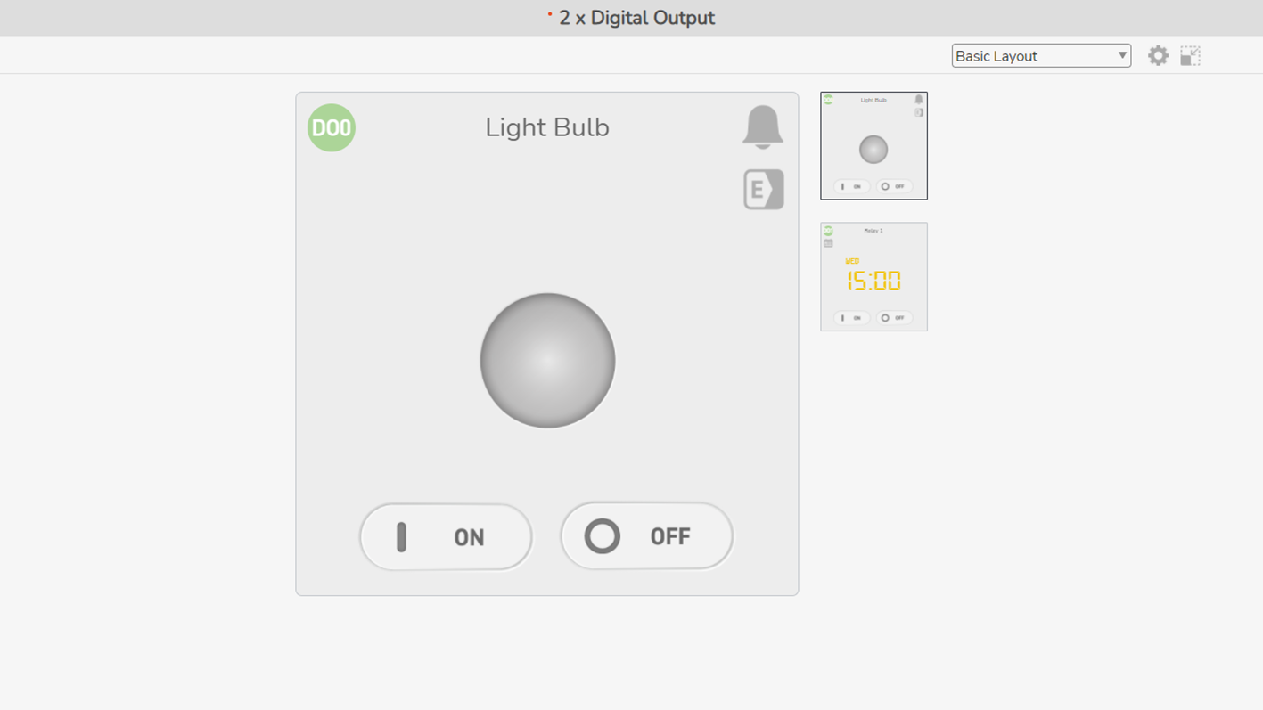
Control via Web: Control by interacting with buttons via Sollae Cloud web app. You can enable up to 2 out of 4 commands. Just click the corresponding button on the digital output widget to send the control command.
Control via Schedule: If you set up the desired date and time, a control command will be sent to the device on the schedule. By default, the Repeat Weekly option is enabled. If you only want it to run once, disable this option.
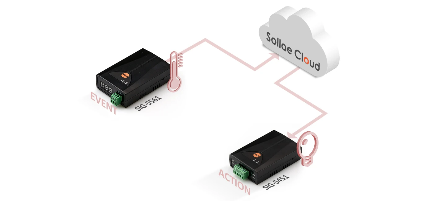
Control via Event-based Action: A control command can be sent to the output port when an event occurs on a Sollae device. For the Sollae analog input device (SIG-5431) or temperature gateway (SIG-5561), after setting up the event condition of the sensor value, you can add a control action so that when the event occurs, the corresponding command will be transmitted to the SIG-5451 output port. For the Sollae digital input device (SIG-5441), after setting up the event condition of the digital input state, you can add a control action so that when the event occurs, the corresponding command will be transmitted to the SIG-5451 output port.
Users can easily control an output port anywhere, anytime, from multiple places and by different methods.
If an output port receives many control commands at the same time, the later-received command will be executed while the previous one will be stopped (see the example below).
Overview
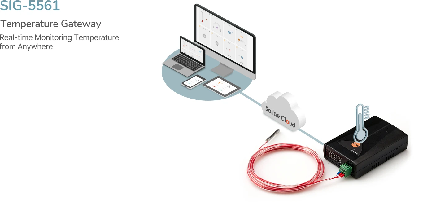
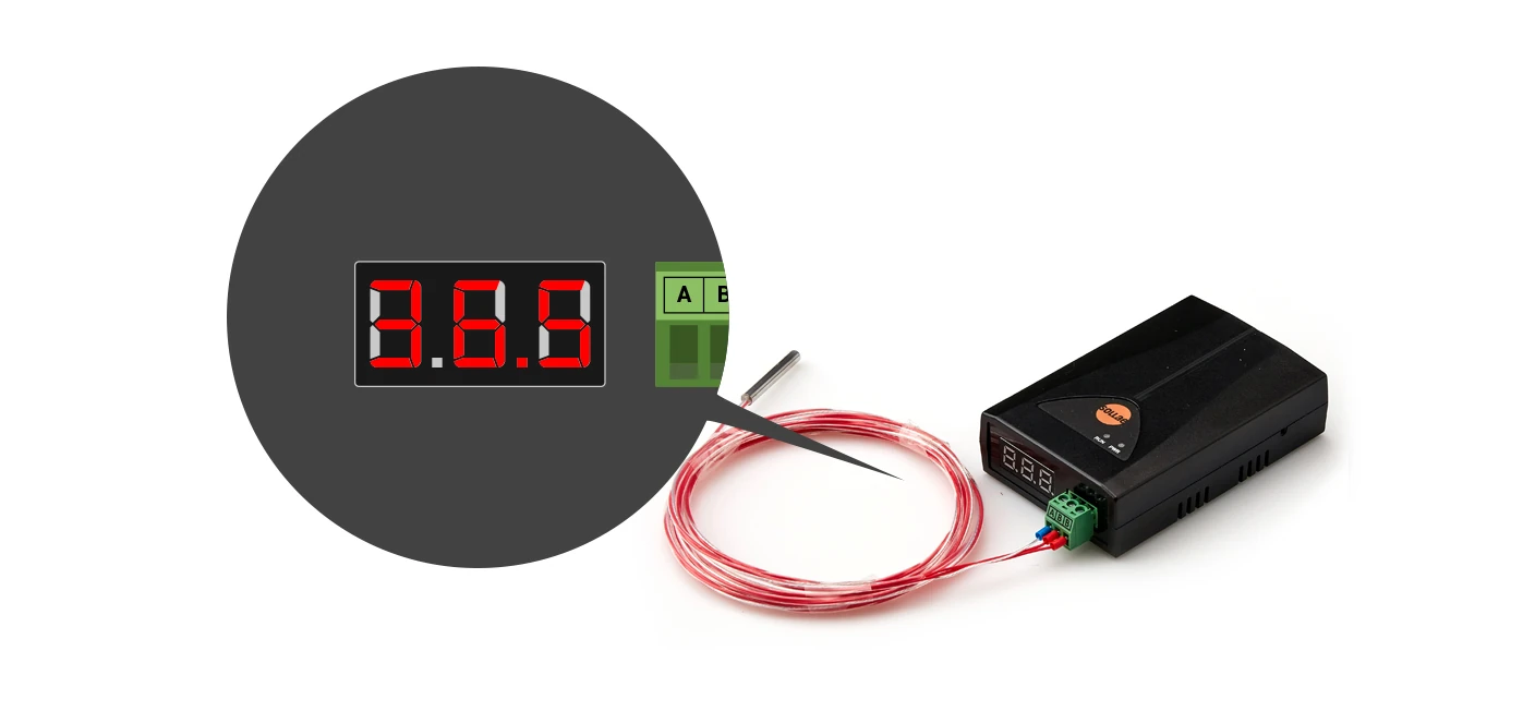
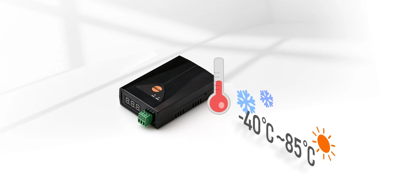
A temperature gateway designed to read temperature values from an industrial PT100 sensor, enabling real-time temperature monitoring.
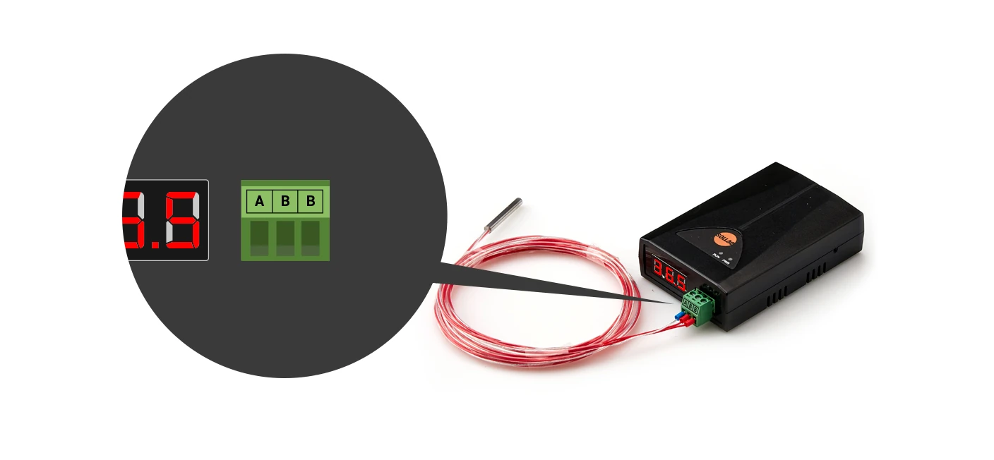
The input port is interfaced with a 3-pole terminal block with 3.5mm spacing, allows easy connection of a 3-wire PT100 sensor. The PT100 probe that we provide separately can support a wide temperature measurement range of -50℃ to 200℃, ensuring accurate monitoring across various industrial applications.
Various widgets provided
Widgets related to temperature display are provided, such as Thermometer, Gauge, 7-Segment LED, Chart, and Progress Bars.
Event
Users can define events and get alarmed when the actual temperature value satisfies the event condition. Alarm effects include a red-blinking visualization on the widget and an alarm sound that is played in the web browser.
The alarm sound is optional and can be enabled each time you start a browsing session.
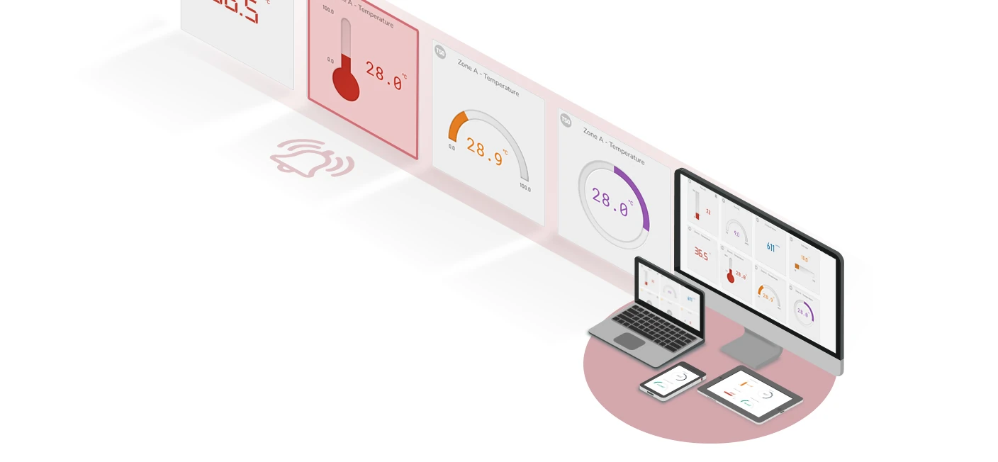
Besides, you can configure event-based actions targeting the Sollae digital output device (SIG-5451/5601), so the output relay can be controlled based on the temperature value.
7-Segment LED
The gateway features a built-in 7-segment LED display that allows instant visualization of temperature measurement values.
Industrial Temperature Specifications
With robust industrial temperature specifications, the gateway ensures reliable operation in extreme temperatures ranging from -40℃ to +85℃.
Multi-monitoring
You can view the temperature value anytime, anywhere, from multiple locations at the same time, either on a PC or mobile.
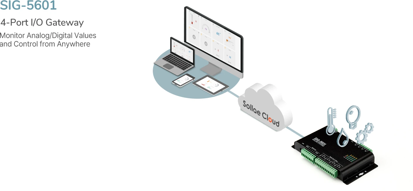
Overview
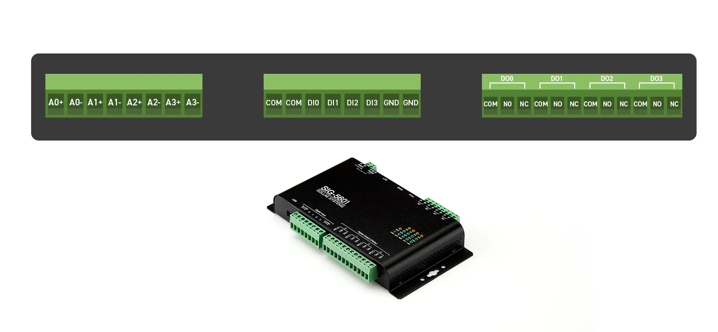
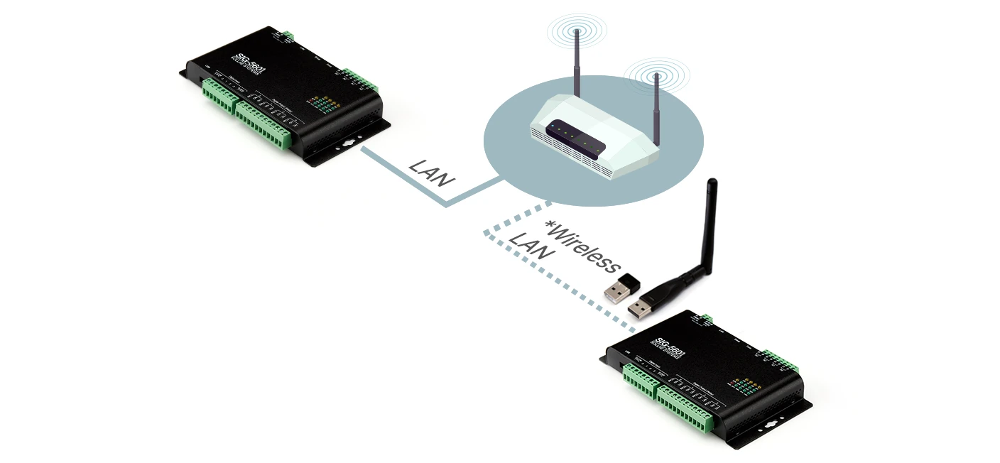
A wired/wireless LAN industrial I/O gateway equipped with 4 analog input ports, 4 digital input ports, and 4 digital output ports, enabling analog/digital sensor value monitoring and output port control anywhere.
The analog input ports are interfaced with a 5mm pitch 8-pole terminal block. The input mode can be selected between voltage (0 ~ 5V), or current (4 ~ 20mA / 0 ~ 20mA). The digital output ports are interfaced with a 5mm pitch 12-pole terminal block. Users can choose between Normal Open and Normal Close mode depending on their application.
Wired/wireless LAN
In addition to wired LAN support, the gateway offers wireless LAN connectivity, enabling wireless connections in environments that require it. For wireless LAN connectivity, a USB wireless LAN adapter (compatible with Ralink's RT3070/5370 chipset) is required.
Various widgets provided
There are several widgets available for analog input, digital input and digital output, you can choose the widget you want for your application.
Event
Users can define events and get alarmed when the actual analog value, digital input or count value satisfies the event condition. Alarm effects include a red-blinking visualization on the widget and an alarm sound that is played in the web browser.
The alarm sound is optional and can be enabled each time you start a browsing session.
In addition, you can configure event-based actions targeting the Sollae digital output device (SIG-5451/5601), so the output relay can be controlled based on the digital input state.
Digital Input Port - Counter
It is possible to count the number of falling and rising edges of the digital input signal.
You can set the counter type, counter direction, and default counter value via web app or spFinder. Those are device-stored, which will make the device disconnected from the cloud for a while when you update those configurations, and then the counter will be reset to the default value.
Digital Output Port - Control Commands
The output ports are controlled remotely via Sollae Cloud. The digital output device will execute the control command after receiving it from Sollae Cloud. There are four commands available. Users can set the delay time for a command, and in case of PULSE, the Width can be set. The maximum Delay/Width operation time can be set is up to 30 minutes (1800 seconds).
Digital Output Commands
ON/OFF: Toggle the state of the output port between ON and OFF.
ON: Turn on the output port.
OFF: Turn off the output port.
PULSE: Keep the output port state as HIGH for the Width time and then turn to LOW.
Digital Output Port - Control Methods
An output port can be controlled by three methods: via web, schedule or event-based actions from Sollae devices.
Control via Web: Control by interacting with buttons via Sollae Cloud web app. You can enable up to 2 out of 4 commands. Just click the corresponding button on the digital output widget to send the control command.
Control via Schedule: If you set up the desired date and time, a control command will be sent to the device on the schedule. By default, the Repeat Weekly option is enabled. If you only want it to run once, disable this option.
Control via Event-based Action: A control command can be sent to the output port when an event occurs on a Sollae device. For the Sollae analog input device (SIG-5431) or temperature gateway (SIG-5561), after setting up the event condition of the sensor value, you can add a control action so that when the event occurs, the corresponding command will be transmitted to the SIG-5601 output port. For the Sollae digital input device (SIG-5441), after setting up the event condition of the digital input state, you can add a control action so that when the event occurs, the corresponding command will be transmitted to the SIG-5601 output port.
Multi-controlling
Users can easily control an output port anywhere, anytime, from multiple places and by different methods.
If an output port receives many control commands at the same time, the later-received command will be executed while the previous one will be stopped (see the example below).
Multi-monitoring and controlling
Monitor, and remotely control via web, schedule, or event-based actions from anywhere.
Sollae Cloud already offers users a plug-and-play solution to monitor and control their devices via a dashboard. Now, Sollae Studio provides a more customizable and flexible solution, in which users can design custom UI to monitor and control their Sollae devices. Besides, with the Share function, the monitoring and controlling features can be shared between users.
The interface
Users can create, view, edit, delete or share their studio, as well as view or remove the shared studio from their list.
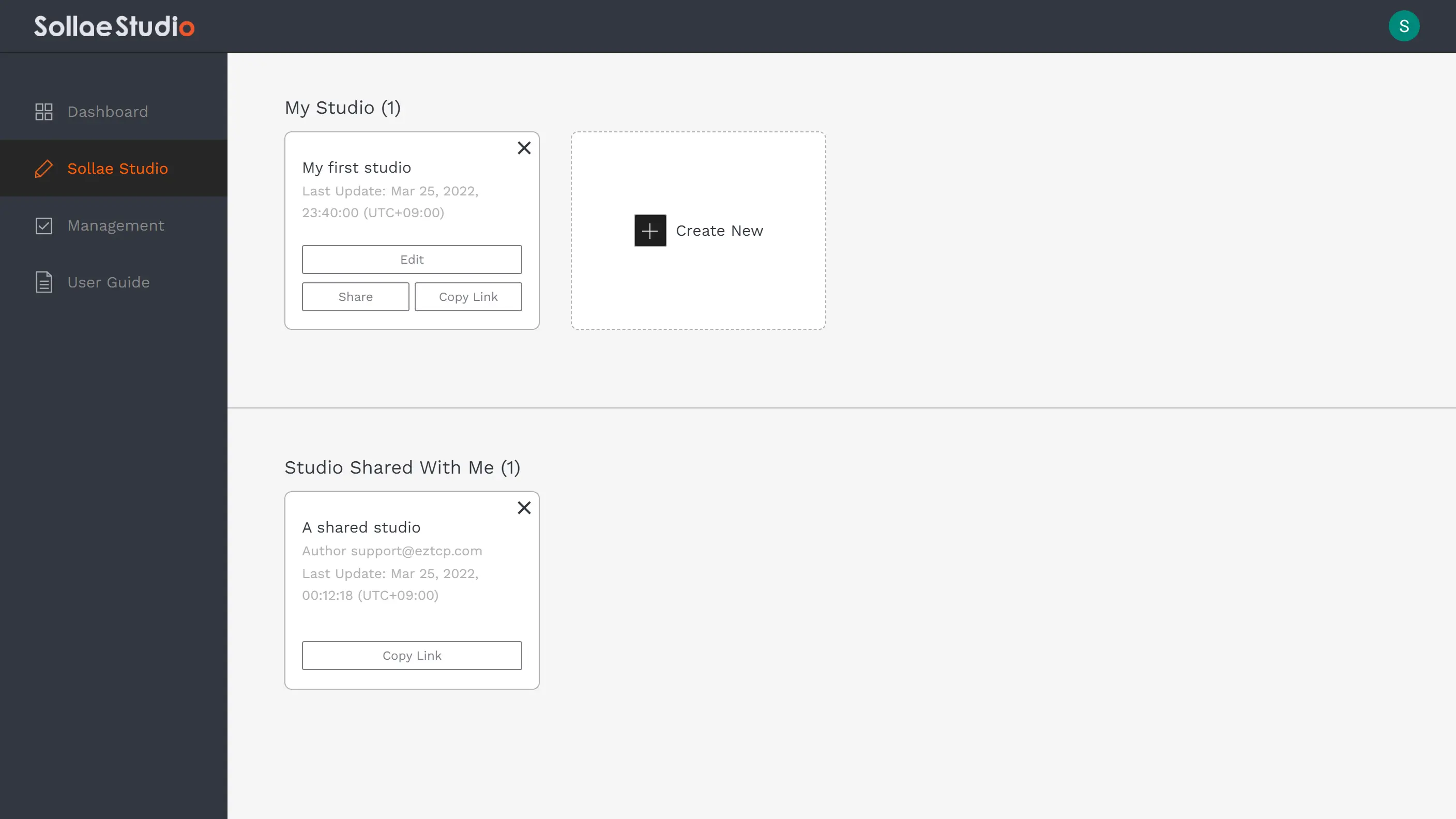
My Studio: Studios created by you. You can create new, view, edit, delete and share the existing studios in this section.
Studio Shared with me: Studios shared with your account. You do not have permission to edit the studios in this section. Removing a studio here simply means excluding yourself from the list of user accounts that have been granted permission by its author to access it.
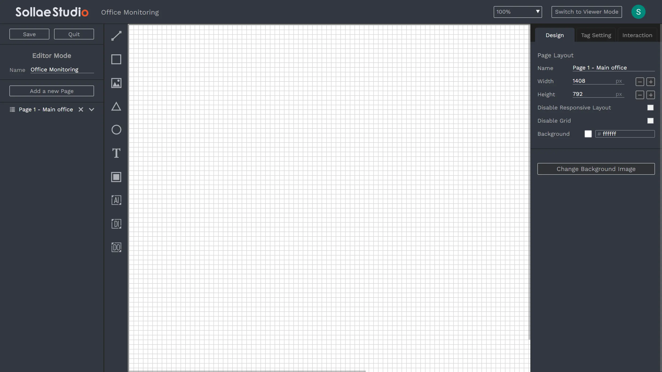
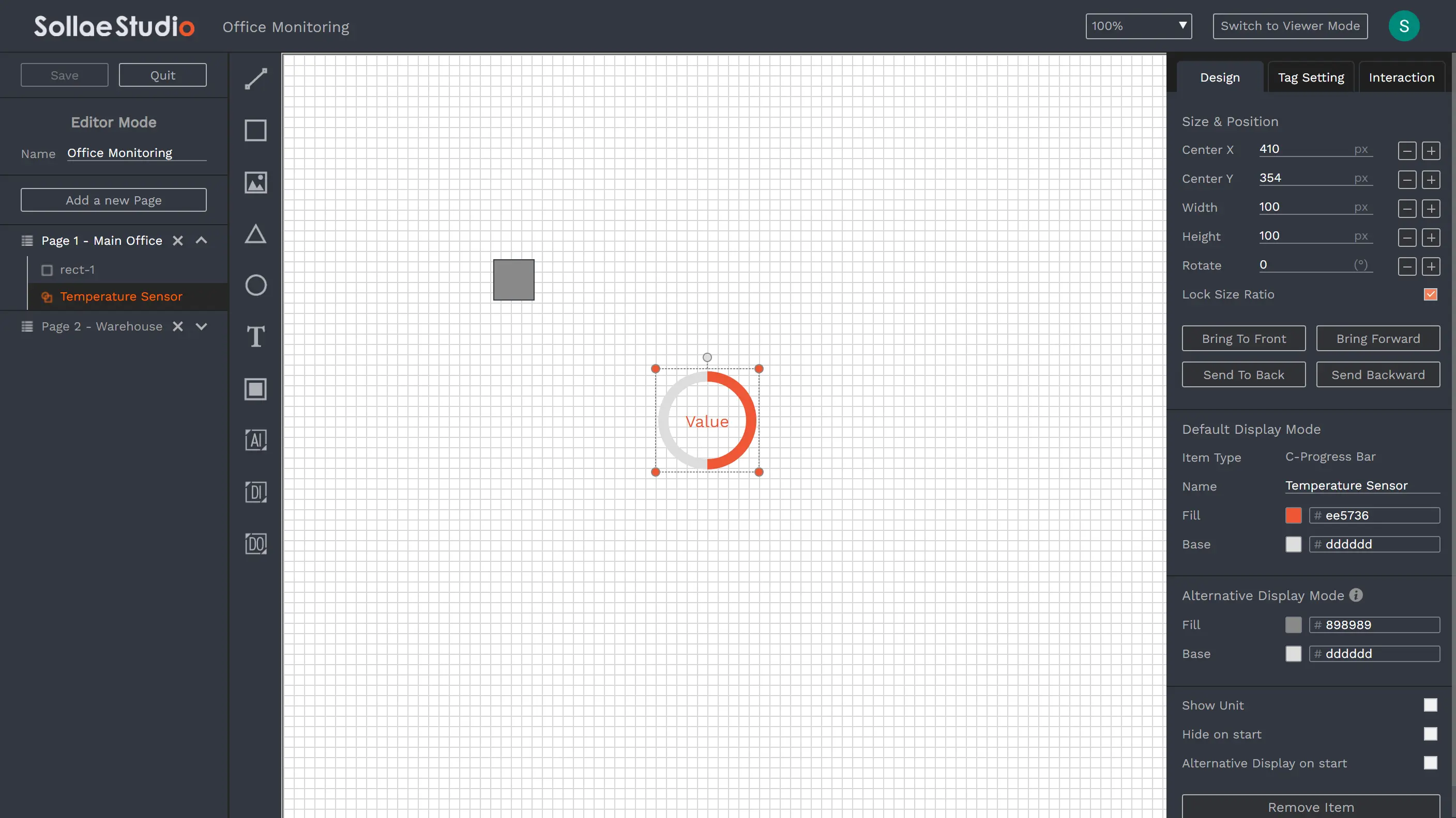
The Editor Mode is where you create your designs for the user interface, and set up monitoring/controlling configuration for the devices.
In the Editor Mode, you can add/remove/edit pages and items, resize, change the position, and do many other things. You can use Editor Mode to design a UI that is fit to be accessed from other screen sizes.
You can enter Editor mode by clicking Create New button, or the Edit button on one of your existing studios. Note that, for an existing studio, only its author can enter Editor mode.
It is recommended to access the Editor Mode from a modern desktop browser. You may use the latest releases of Chrome, Edge, Firefox, or Safari.
The minimum requirement for the browser screen size to enter the Editor Mode is 800px width and 500px height.
The minimum requirement for the browser screen size to enter the Editor Mode is 800px width and 500px height.
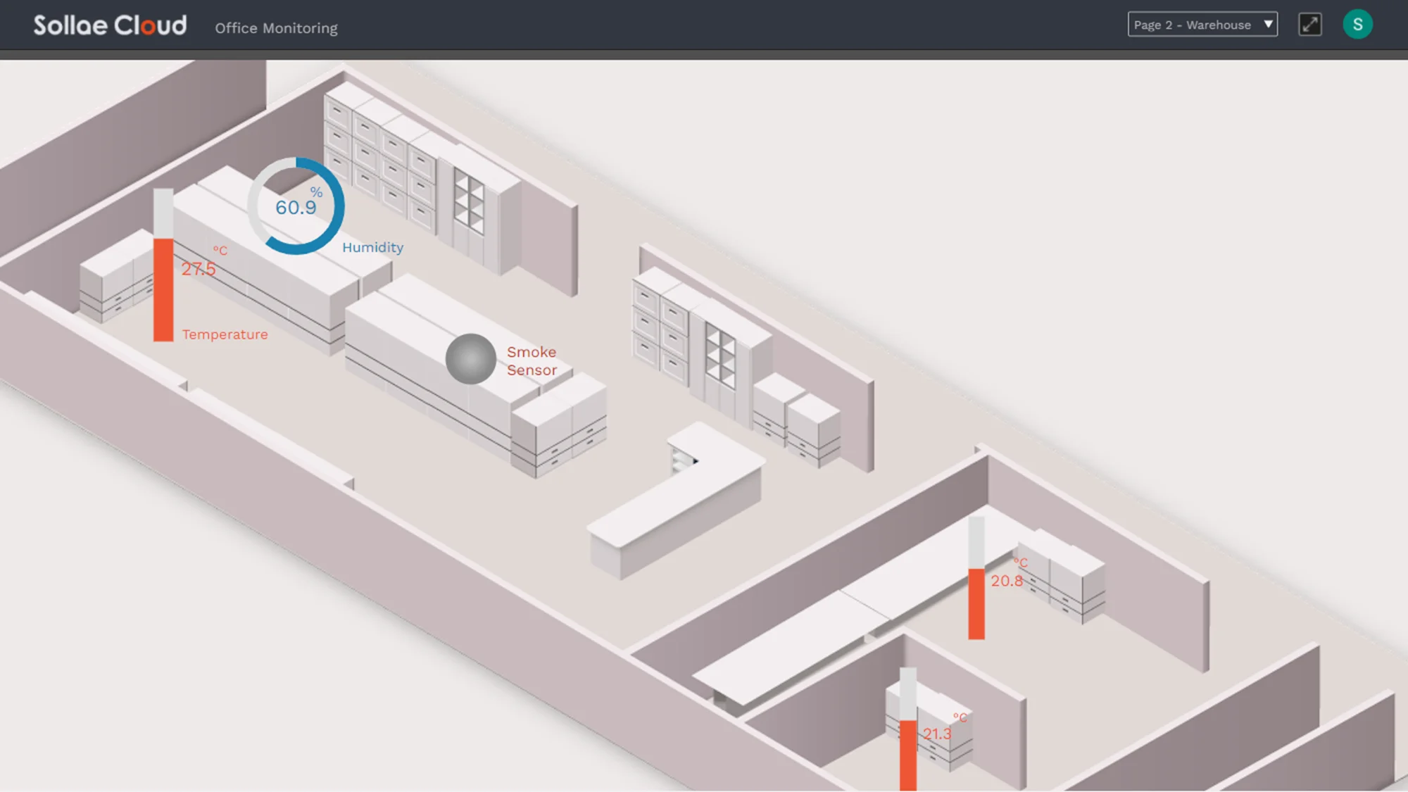
Launch and interact with the studio designed by you or shared with you.
First, a studio is created in the Editor Mode, which should be done on a modern desktop browser. After that, it can be viewed from any browser supported by Sollae Cloud, including mobile browsers. You can then interact with a highly customized UI to monitor and control your system. For better user experiences, we suggest that you access the Viewer Mode from modern browsers.
The Alarm function is supported in Sollae Studio. When an alarm set for a port occurs, the widget linked to the port will have a blink effect. You may also click on the blinking widget to dismiss the alarm.
Read more: Alarm Function
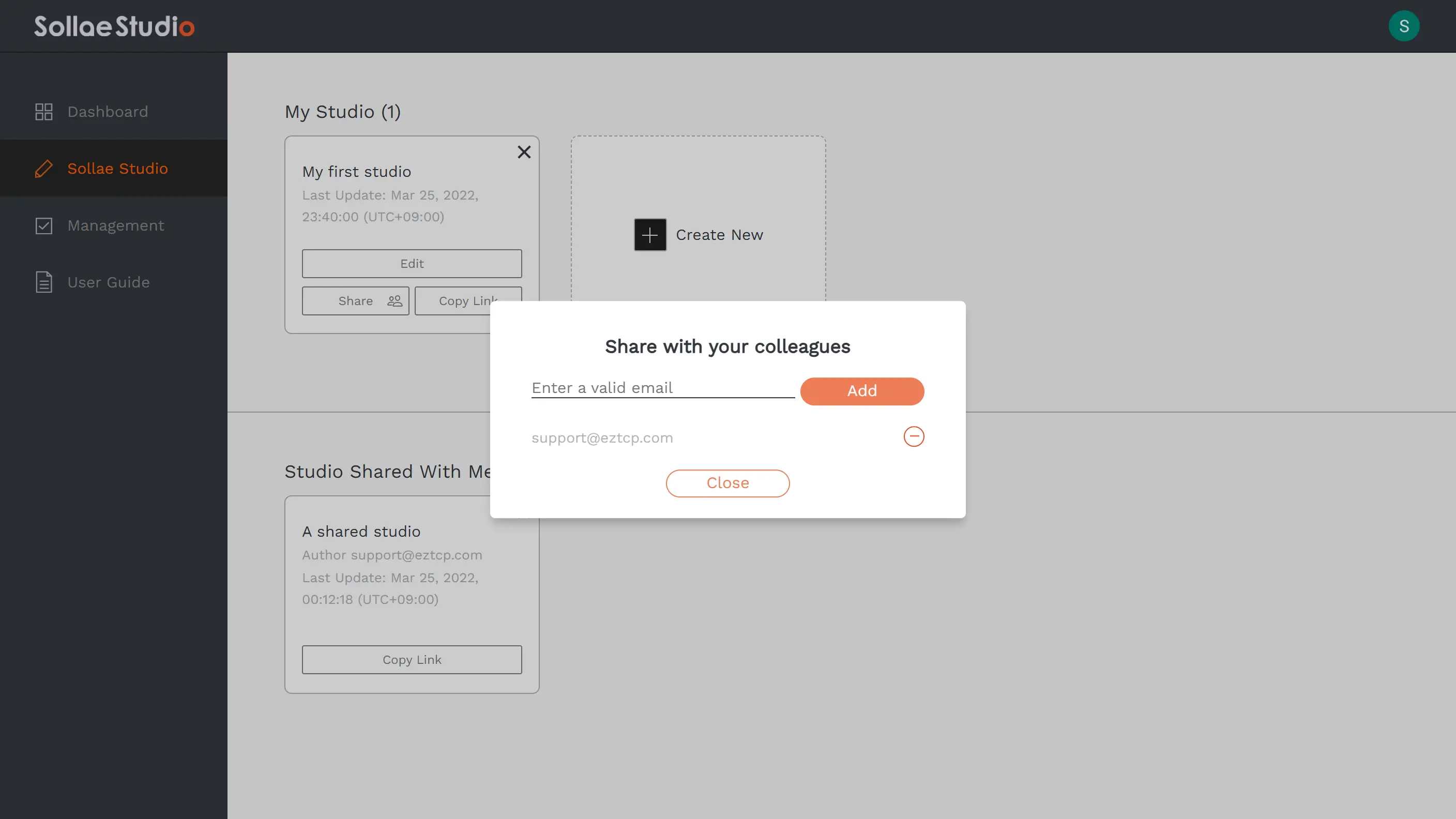
You can share your studio with other Sollae Cloud users. Before sharing a studio with your colleagues/friends, make sure they have a valid Sollae Cloud user account. A valid Sollae Cloud user is an account that has been already signed in to Sollae Cloud, thus agreeing with our Terms of Use. Click the Share button on your existing studio to update the sharing setting.
Note that, after a device is set to be monitored/controlled via a studio, the permission to monitor and control it will be granted to those who you share the studio with. You can add or remove a user from the share list of your studio at any time.
The Alarm function works in a shared studio. If the author set up alarms for a port in a shared studio, anyone who has the studio shared with them can be alarmed when an event on the port occurs.
Those who have a studio shared with them are not able to enter the Editor Mode of the shared studio, thus they can not make any modifications. They can give up their view permission for a studio, by which the studio will be removed from their Studio Shared with me list. The Edit/Delete permission is given solely to the author of the studio.
Each studio can be shared with up to 20 users.
Each studio can be shared with up to 20 users.
In Sollae Studio workspace, there are three categories of elements. The first category is studio, the second is page, and the third is item. A studio may consist of many pages, and within a page, there are items attached to it.
As an example, let's say you want to monitor your office using your sensors. You can create a studio for this application, in which the monitor screen of each office room is equivalent to a page. On each page, you can use items to design UI, and link them with the sensors to build up a monitor screen.
Studio
Page
Item
Studio
A studio is built from pages and items. You can change the name of the studio, and add pages and items to it in the Editor Mode. You can also share your studio with your friends and colleagues.
The maximum number of studios you can create = The number of your registered devices + 2.
Page
You can update the size, change the name, or add a background image to a page. On a page, you can add, edit and remove items.
The maximum number of pages per studio is 20.
Item
There are several types of items that enable you to make up your own design. An item must be attached to a page. Adding an item to a studio means adding it to a page within the studio. In the Editor mode, you can change the style, position, and layer of the items.
Line
Rectangle
Triangle
Ellipse
Image
Text Box
Button
Analog Input Widget
Digital Input Widget
Digital Output Widget
The maximum number of items per page is 200.
You can add a background image to a page or create Image items for your design. For Image items, you can use the common images provided by us or upload custom images. Each user can upload up to 16 images, and the maximum size of each custom image is 1MB.
You can add a background image to a page or create Image items for your design. For Image items, you can use the common images provided by us or upload custom images. Each user can upload up to 16 images, and the maximum size of each custom image is 1MB.
Read more: Items of Sollae Studio
Items are primitive components to make up pages and studios. You can use items to build up UI, and link them to the Sollae device ports for remote monitoring/controlling functions.
Basic Items
Core elements used for designing layouts and user interfaces:
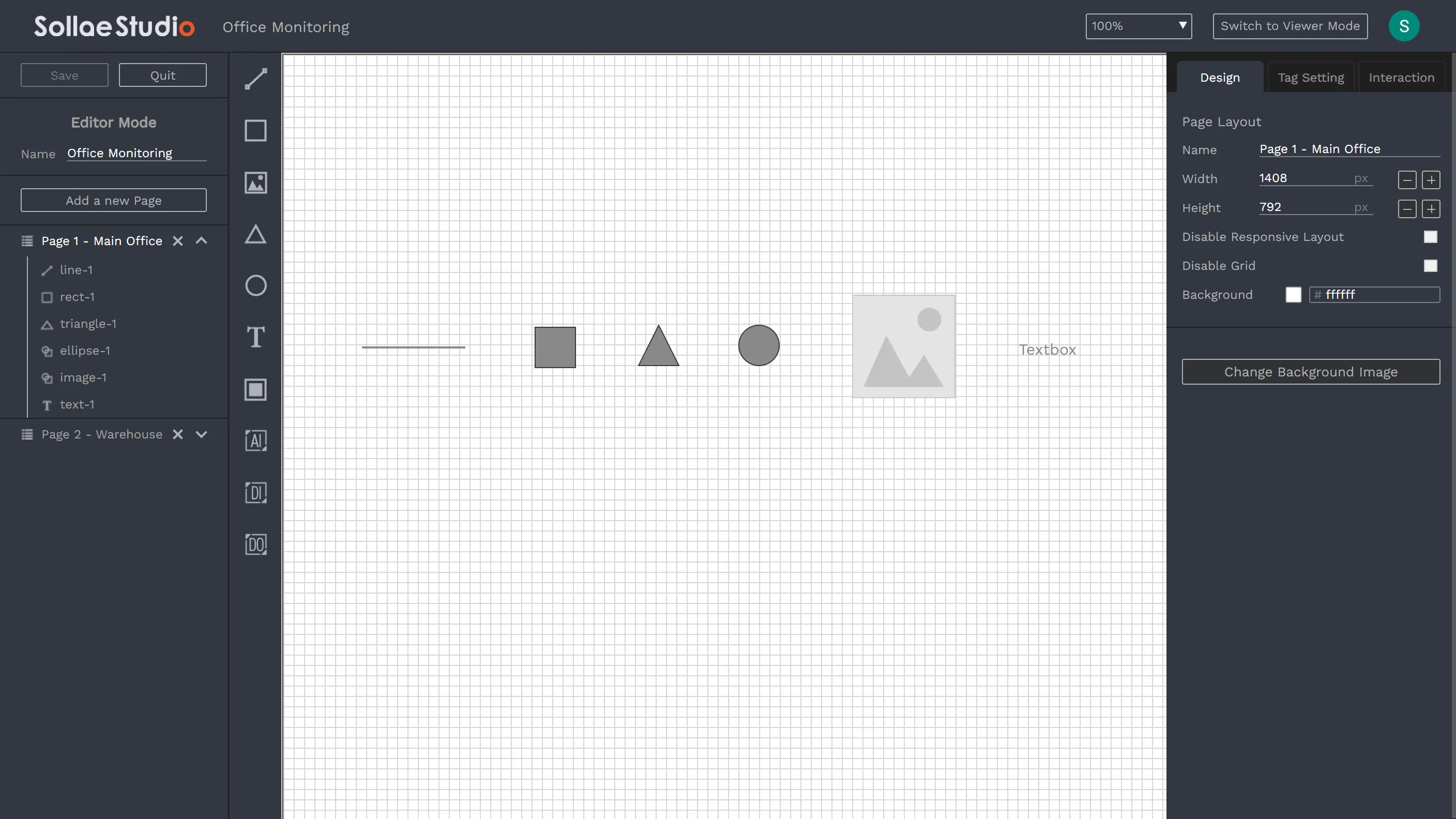
Line
Rectangle
Triangle
Ellipse
Image
Text Box
Button
Like a basic item, a Button can be used to create the layout and user interface. It also supports sending control commands, similar to a digital output widget.
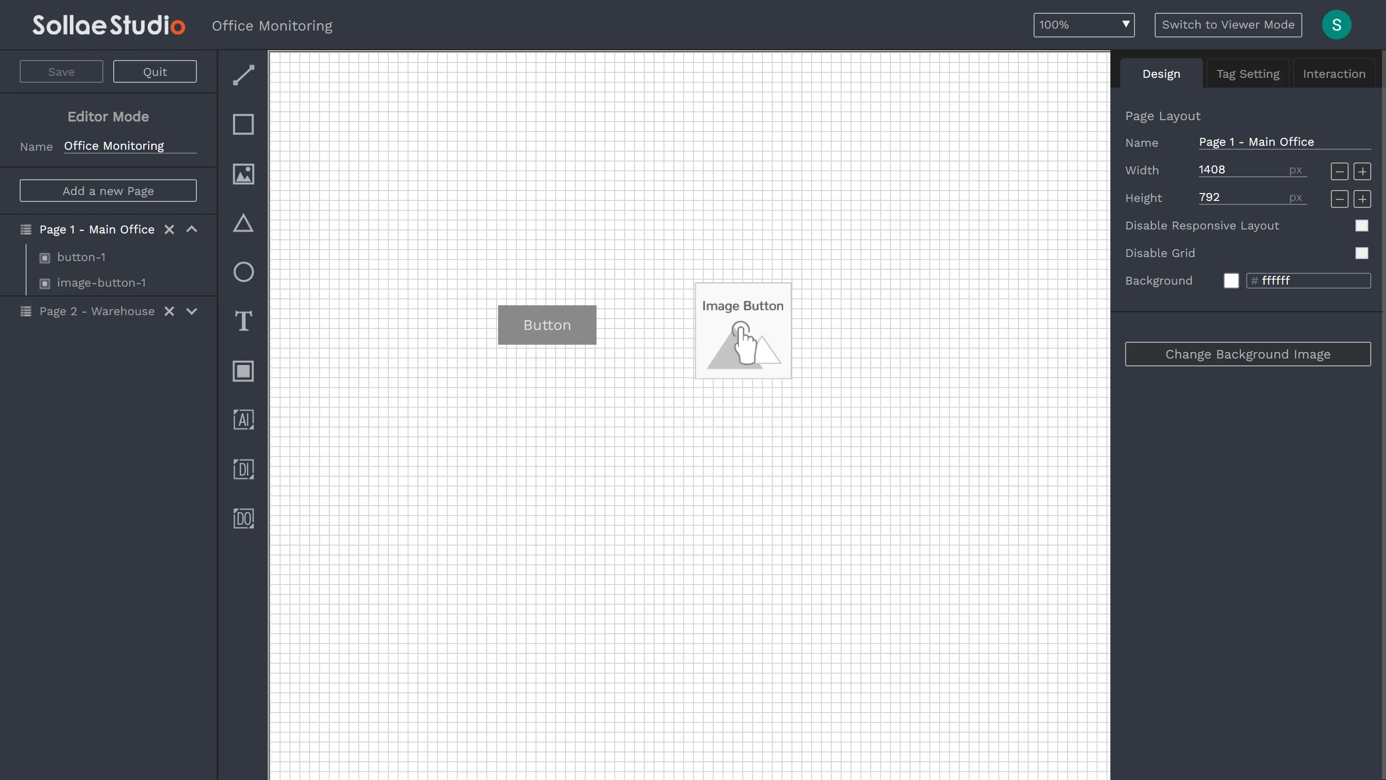
Basic Button: Standard button element
Image Button: Custom button using images
Analog Input Widget
Used to link with analog input ports for real-time monitoring. Five types of widgets are available to visualize analog input data:
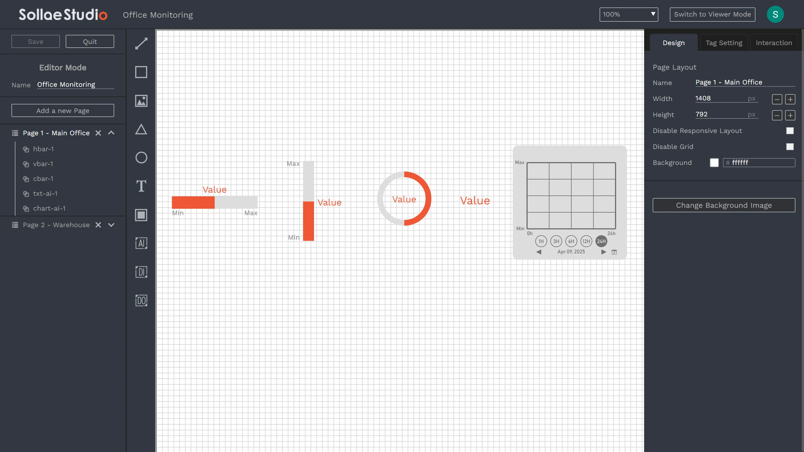
Horizontal Progress Bar
Vertical Progress Bar
Circular Progress Bar
Text AI
Chart AI
Digital Input Widget
Used to link with digital input ports for real-time monitoring. Four types of widgets are available to visualize digital input states:
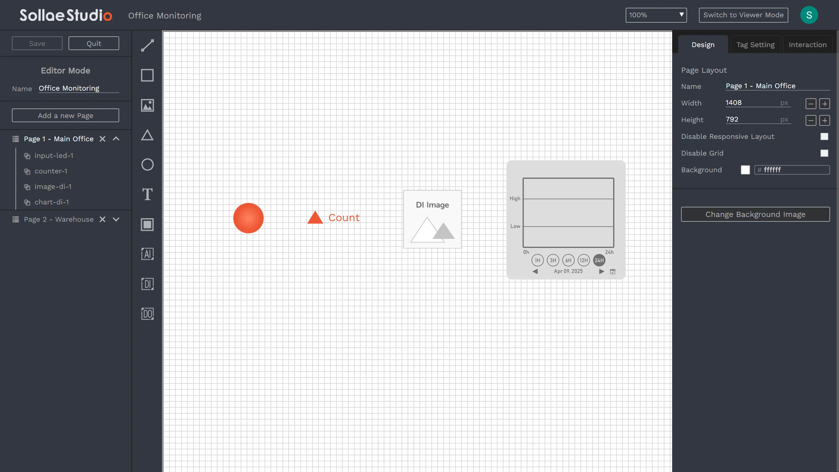
Input LED
Counter: Display count value with state indicator. Not available for SMG models.
Image DI: Custom images for ON/OFF states
Chart DI
Digital Output Widget
Used to link with digital output ports for real-time monitoring and remote control. Five widget types are available:
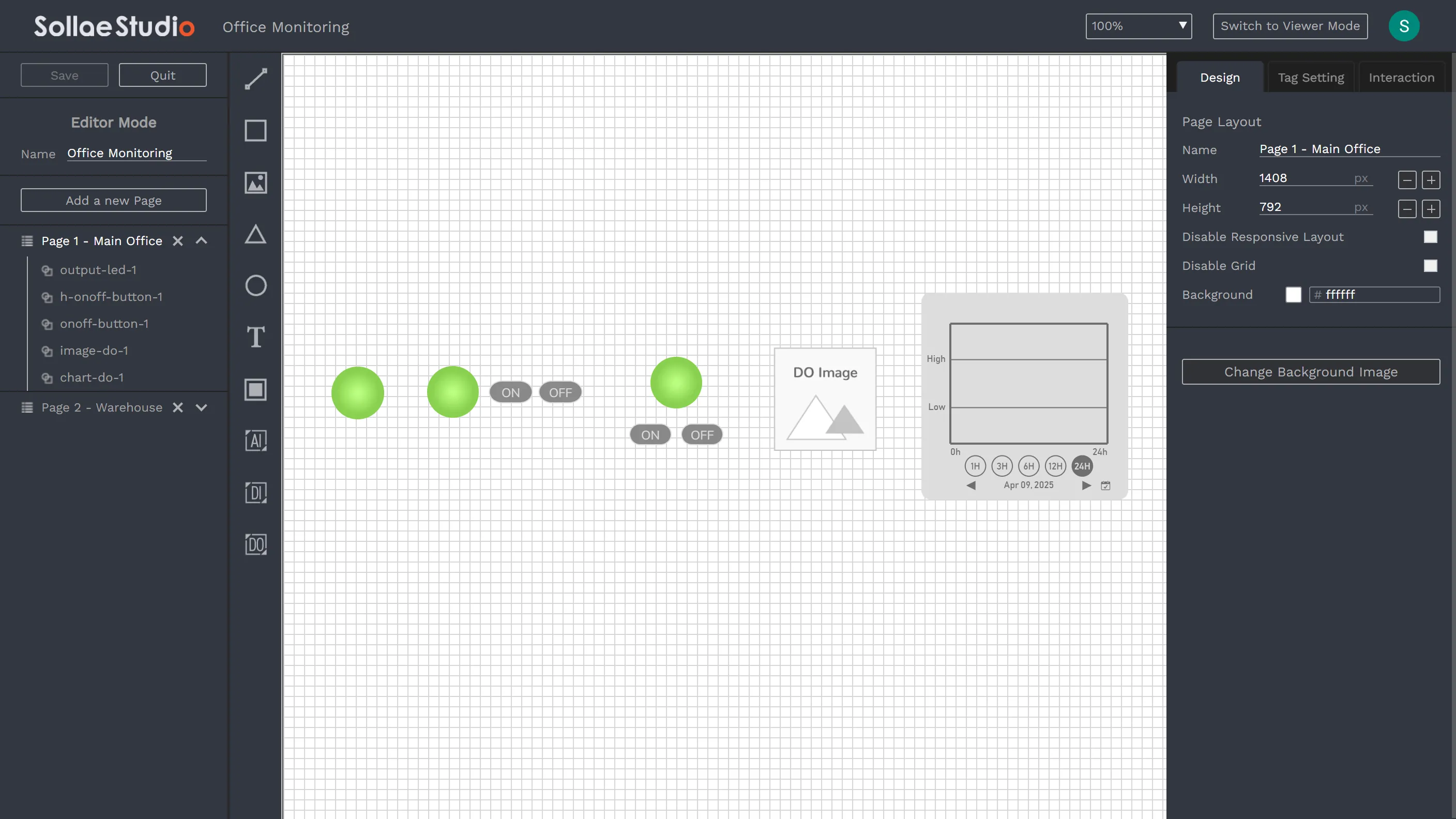
Output LED: Visual indicator for port state with toggle functionality. Click to toggle ON/OFF state. Note that, when tagged to SMG models, it only supports state monitoring without toggle functionality.
Horizontal ON/OFF
Vertical ON/OFF
Image DO: Custom images for ON/OFF states with toggle functionality. Note that, when tagged to SMG models, it only supports state monitoring without toggle functionality.
Chart DO: Support monitoring only, no control functionality.
In addition to digital output widgets, you can also configure Buttons to send custom control commands to digital output ports.
Design
Design layout and change visualization style for your studio.
Page Layout
Page Name
Width and Height: You can set it to fit a mobile phone, your PC screen size, another PC screen size, etc, where the page will be viewed from. The default value is set based on the screen size of the PC where you created the studio.
Responsive Layout: Automatically adapt view to different screen sizes (enabled by default). When disabled, pages will render at their exact specified width and height.
Grid Mode: Only applied for the Editor Mode
Background Color/Image
Item Size & Position
Position and Layer
Width and Height
Rotation
Lock Size Ratio: Maintain width-to-height proportions when resizing (enabled by default for widgets, Image, and Image Button).
For general use, the Default Display Mode may be enough to visualize an item. Sollae Studio provides two display modes for users who need a higher level of customization. The display modes are designed for enabling UI effects when using Interaction. Users can set up two display modes for an item beforehand, and add interaction to change the display mode. After that, in Viewer Mode, users can interact with items and see the UI effects as per design.
Read more: Sollae Studio - Interaction
Tag Setting
Set up Tag Setting to link the widget to Sollae device. Only available for AI, DI, DO widgets, and Button, not for the Basic items.
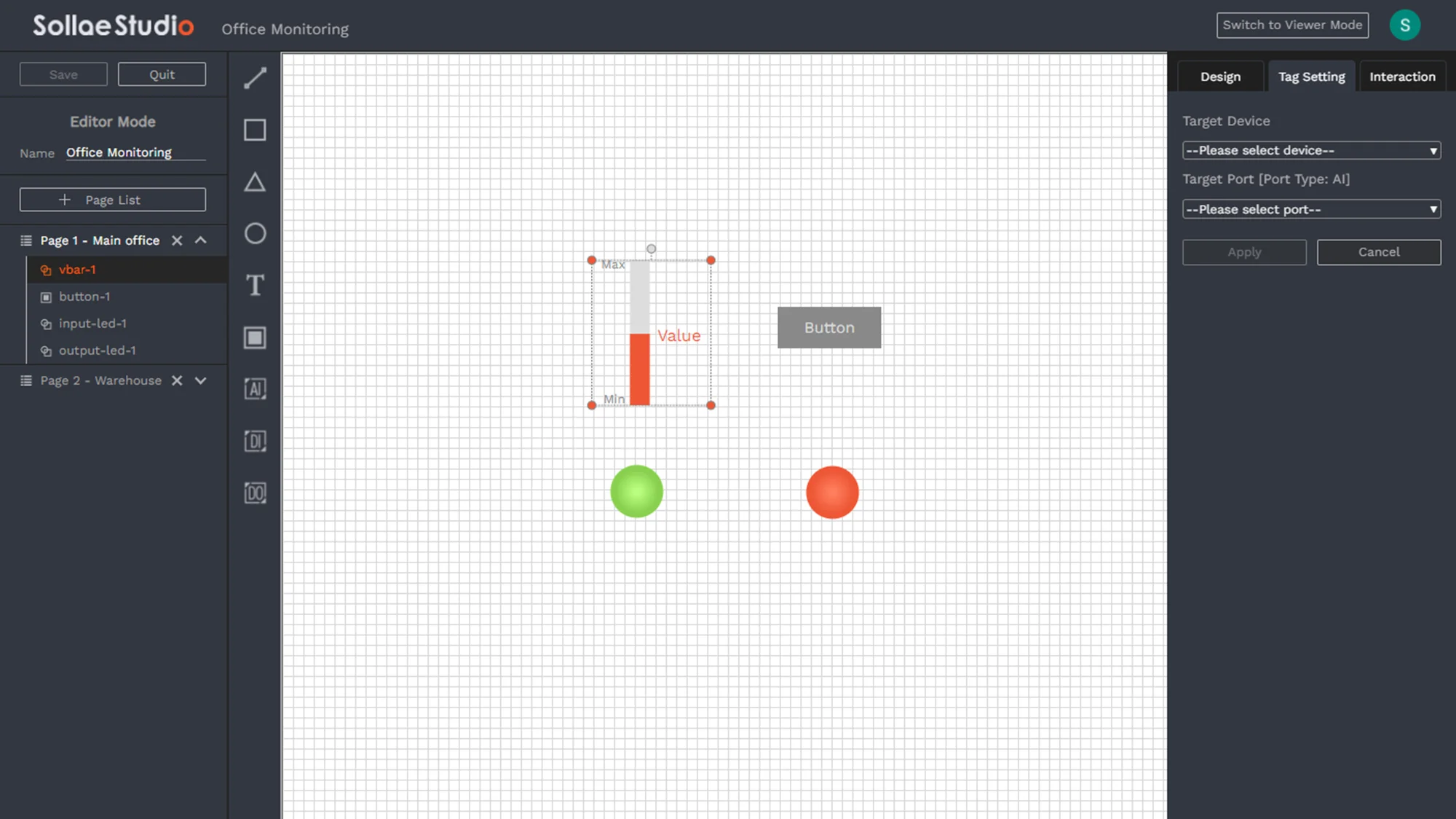
As in the Dashboard page, a device is represented by multiple widgets that allow you to monitor and control each port of the device. Similar to that, in Sollae Studio, a widget can be used to control and monitor the port. A required step is to add a widget item and tag it with a port in a Sollae device. By setting up this, you will be able to control and monitor the device in real-time.
Set up mouse interaction for items. Only available for the Basic items and Button, not for AI, DI, and DO widgets.
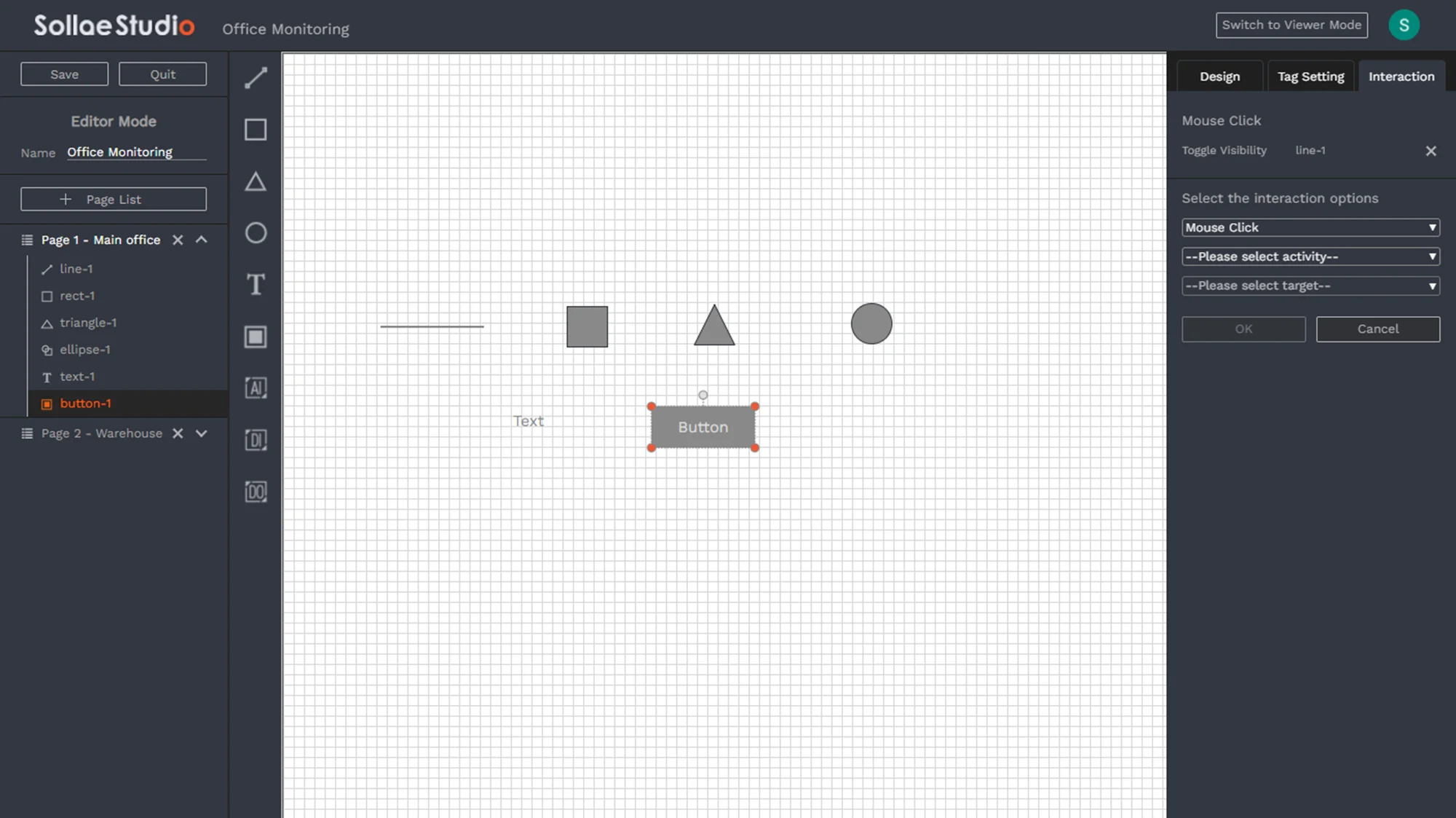
Interaction Type
Mouse Click
Interaction Activity
Show: Set an item to be visible
Hide: Set an item to be hidden
Toggle Show/Hide: Toggle visibility of an item
Set to Default: Set an item to the Default Display mode
Set to Alternative: Set an item to the Alternative Display mode
Toggle Default/Alternative: Toggle the display mode of an item
Navigate to Page: Used to navigate between pages in one studio
Send Digital Output Command: Used to send a custom control command to a digital output port. Only available for Button
The interaction activities from 1 to 6 are available between items on the same page since only intra-page interaction is supported.
Below are some shortcuts that can be used while editing a studio.
| Function | Windows/Linux | MacOS |
|---|---|---|
| Item multi-select | CTRL + Mouse click | ⌘ + Mouse click |
| Resize an item with a fixed ratio | SHIFT + Mouse move | SHIFT + Mouse move |
| Resize an item with center positioning | ALT + Mouse move | ⌥ + Mouse move |
| Move the selected item | ← ↑ → ↓ | ← ↑ → ↓ |
| Duplicate the selected item | CTRL + C | ⌘ + C |
| Paste the copied item | CTRL + V | ⌘ + V |
| Delete the selected item | DEL / BACKSPACE | DEL / BACKSPACE |
| Cancel creating a new item | ESC | ESC |
| Undo | CTRL + Z | ⌘ + Z |
| Redo | CTRL + Y | ⌘ + Y |
Users can also access the quick menu with a Right mouse click.
If you have any further inquiries about Sollae IoT Cloud solution, feel free to reach us at sales@eztcp.com. For technical support, you may contact us via support@eztcp.com.
If you wish to quickly turn the sensor/equipment around you into Internet-connected, or make any IoT application, then Sollae Cloud is for you. You will be able to do many things via the Internet:
Monitor real-time data from sensors and equipment
Control relay output remotely
Set up schedules or define events to automatically control output
Get alarmed on the edge cases within your system
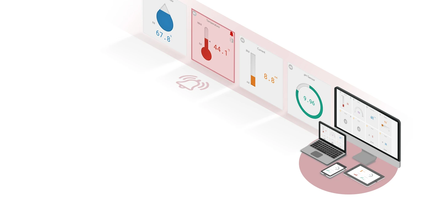
And a lot more to make your life easier
Real-time monitoring of a thermometer, controlling a light bulb, etc, can be done via the Internet with the help of Sollae Cloud. You can easily build your own IoT system, monitor, control, and manage it via the Sollae Cloud. We offer a user-friendly web UI, a secure, reliable service that is available 24/7 and accessible from anywhere.
No, you may need to sign up for a Google account then.
It is free for the basic service. You just need to have a Sollae Gateway for Cloud in order to use the common features of Sollae Cloud.
To access your sensor/equipment via Sollae Cloud, you need to connect it with a Sollae IoT Gateway device. Sollae Cloud web app provides the user interface, while Sollae IoT Gateway device is the one that executes the job. Sollae IoT Gateway devices are equipped with analog input, digital input, and digital output ports, following industry standards. They act as a bridge between users and the IoT equipment, in that they interface with sensors/equipment on one side and exchange data with Sollae Cloud on the other side.
First, see if your device is a Sollae Gateway device supported by Sollae Cloud. Please make sure the device is connected to the Internet. Follow the device registration process and double-check if you enter the correct device client ID.
Before trying again, it is also recommended to use spFinder to check and update your device's firmware to the latest version.
Note that, you cannot register a device that is currently registered to another account on Sollae Cloud.
Yes, you can. There are two ways you can share access to your devices.
The first is to share via a common account. If many people want to share the access permission of a device in Sollae Cloud, they can register it to a common account. Then, everyone can sign in with that account and access the device.
The second method is sharing via Sollae Studio. You can share the monitor/control permission of your devices with other Sollae Cloud accounts.
It means many Sollae Cloud web app windows are being opened simultaneously, and that has exceeded the limitation of your account. In the web app window which has this message displayed, you cannot monitor/control or configure your registered devices, but you are still able to register new devices to your account. To continue, please close other web app windows you are not using, or register new devices to increase the number of access allowed for your account, and after that reload the web page.
The maximum number of simultaneous access is the number of registered devices plus two. For example, if an account has 3 registered devices, it allows up to 5 access simultaneously. However, one Dashboard, Management or Studio browsing tab is counted as one access. If you open N tabs for these pages on the same or different browsers, it will be considered as N access.
Follow these steps to migrate to Sollae Cloud V3:
Log in to Sollae Cloud V2.
Follow the Remote Firmware Update instruction to update the latest firmware to your device.
After the firmware update, you will notice the ***V3 Migrated prefix in the Device List.
Log in to Sollae Cloud V3 to access and manage your migrated devices.
Sollae Cloud V2 is scheduled to end its service on September 06, 2023. Until the scheduled end date, both Sollae Cloud V2 and V3 will coexist, allowing users to access and manage their devices without interruption. However, after the end of service date, Sollae Cloud V2 will no longer be accessible, and users will only be able to utilize Sollae Cloud V3 to continue using the platform's features and functionalities. To avoid any service disruption, it is crucial to migrate all your Sollae IoT Gateway devices to V3 before this date.
After the scheduled end of service, you can manually upgrade to version 3 by using spFinder to update the firmware on your Sollae IoT Gateway devices. Once updated, you can log in to Sollae Cloud V3 to continue managing, monitoring, and controlling your devices.
April 2025
Upgrade to Sollae Cloud version 3.3.
Add file encoding option to log downloads.
Improve Sollae Studio with multi-select, zoom and responsive layout.
Add image and chart widget support to Sollae Studio.
Fix chart widgets and stability issues.
Add Interframe Gap for Modbus queries.
August 2024
Upgrade to Sollae Cloud version 3.2.
Fix UI issues for chart and Modbus data handling.
Enhance system security.
Optimize database performance.
May 2024
Upgrade to Sollae Cloud version 3.1.
Support SMG models (Modbus Gateway to Cloud)
Introduce Email Notification
Add Chart widgets for viewing historical data
July 2023
Upgrade to Sollae Cloud version 3.
Powered by AWS IoT Core for enhanced functionality compared to version 2
Introduce Device Data Logging
Remote Firmware Update function is now enabled
June 2022
Upgrade to Sollae Cloud version 2.
Add the graphical editor tool: Sollae Studio
Newly supported device: SIG-5561 (Temperature Gateway)
Temporarily disable the Remote Firmware Update function
Remove Naver login for Korean users
2021
Sollae Cloud is released.